clutch master cylinder

A clutch master cylinder and housing technology, applied in clutches, fluid-driven clutches, non-mechanical drive clutches, etc., can solve the problems that the sealant cannot withstand high pressure, the strength of the metal insert cannot be reached, and the risk of seal failure is high. Avoid surface treatment process, good injection molding process, and ensure the effect of consistency

Active Publication Date: 2019-06-28
ZF COMMERCIAL VEHICLE SYSTEMS (QINGDAO) CO LTD
View PDF7 Cites 0 Cited by
  • Summary
  • Abstract
  • Description
  • Claims
  • Application Information

AI Technical Summary

Problems solved by technology

Conventional insert injection molding due to the material difference between the plastic substrate and the metal insert, the thermal expansion coefficient is different, a gap will be formed between the plastic and metal insert, and the risk of seal failure is high. In addition, the joint insert is affected by the thread torque during assembly. Will increase the risk of leakage, resulting in product failure
[0004] In order to solve the sealing problem, there are currently two commonly used solutions: one is to use high-strength plastic joints instead of metal joints as inserts to reduce the difference in thermal expansion with the plastic base material, but the high-strength plastic joint inserts cannot reach the metal inserts. There is a risk of damage when assembling high-torque joints; the other is to add sealant between the insert and the plastic substrate, but the sealant cannot withstand high pressure, and it can only be used for low-pressure dustproof and waterproof sealing. There is still a risk of failure in high-pressure gas or oil applications

Method used


Image

  • clutch master cylinder
  • clutch master cylinder
  • clutch master cylinder

Examples


Embodiment Construction

[0036] The present invention will be further described in detail below in conjunction with the accompanying drawings and specific embodiments, but the present invention is not limited to these embodiments.

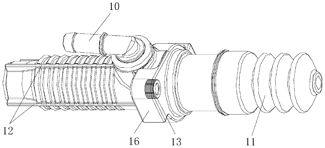
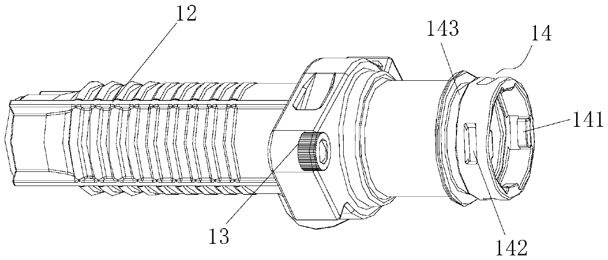
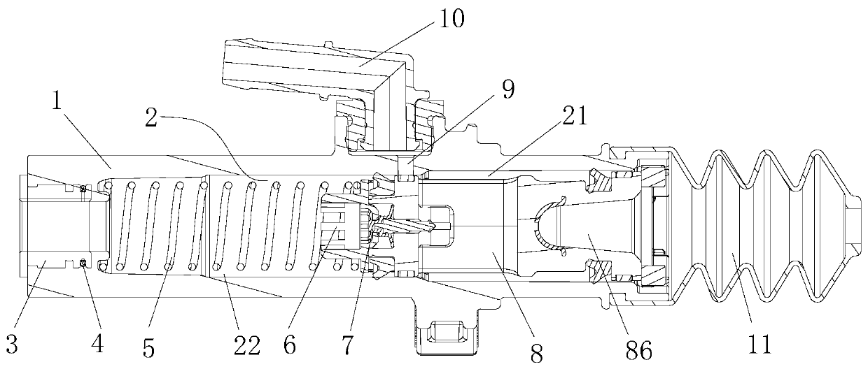
[0037] Such as Figure 1 to Figure 10 As shown, the clutch master cylinder includes a housing 1 made of plastic. A plurality of reinforcing ribs 12 are uniformly distributed along the axial direction of the housing 1 around the outer circumference of the housing 1, and the reinforcing ribs 12 are made of plastic. The outer side of the housing 1 is provided with a flange plate 16 for realizing the installation and positioning of the housing 1. The flange plate 16 is made of plastic, and the flange plate 16 is located on the right side of the reinforcing rib 12. In the positioning hole, a second metal insert 13 is arranged in the positioning hole, which ensures the installation strength. The right end of the housing 1 is provided with a dustproof cover 11 connected thereto...


PUM


Abstract

The invention discloses a clutch master cylinder, and belongs to the technical field of automobile parts. The clutch master cylinder comprises a shell. An oil inlet and an oil outlet are formed in theshell. A cavity and a piston are arranged in the shell. A connector insert is arranged at the oil outlet and is made of metal. A seal ring is arranged between one end of the connector insert and theinner wall of the oil outlet. A seal groove matched with the seal ring is formed in the periphery of the connector insert in the circumferential direction. The shell is made of a plastic base materialthrough injection molding, the seal ring is assembled into the seal groove of the connector insert before injection molding, and the shell is formed by the connector insert, the seal ring and the plastic base material through injection molding. According to the clutch master cylinder, the shell is made of plastic suitable for a brake fluid environment, and metal inserts are arranged at the oil outlet of the shell and the installation interface of a flange plate, so that the structural strength of the clutch master cylinder is improved, the clutch master cylinder can replace most existing clutch master cylinders with metal shells, and the purposes of machining cost reduction and lightweight design of automobiles are realized.

Description

technical field [0001] The invention belongs to the technical field of auto parts, in particular to a clutch master cylinder. Background technique [0002] Most of the traditional clutch master cylinders use cast iron or cast aluminum metal shells to meet the requirements of high-precision dimensions through machining and the requirements of surface treatment to achieve corrosion resistance. Although high-strength plastics have been widely used in the automotive field, due to high hydraulic pressure and brake fluid resistance requirements in clutch master cylinder applications, high-strength plastics are rarely used to make clutch master cylinders. [0003] Due to the problem of plastic strength, when replacing the metal shell, it is necessary to add metal inserts to ensure the same installation strength and sealing requirements as the metal shell. In addition to realizing the installation function, metal inserts are required to be embedded in joints in many applications to...

Claims


Application Information

Patent Timeline
Patent Type & Authority Patents(China)
IPC IPC(8): F16D25/12F16J15/06F16J9/12
CPCF16D25/126F16J9/12F16J15/064
Inventor 李秋爽高宁山
Owner ZF COMMERCIAL VEHICLE SYSTEMS (QINGDAO) CO LTD
Why Eureka
Try Eureka