
Voltage responding-type permanent magnet synchronous machine and simulator of driving system of voltage responding-type permanent magnet synchronous machine

A permanent magnet synchronous motor and drive system technology, applied in the field of simulators, can solve the problems of increasing the loss of the test system, difficult to freely change motor characteristics, difficult to simulate complex, high dynamic load torque characteristics and other problems

Active Publication Date: 2018-05-04
SHANGHAI JIAO TONG UNIV
View PDF5 Cites 5 Cited by
  • Summary
  • Abstract
  • Description
  • Claims
  • Application Information

AI Technical Summary

Problems solved by technology

[0004] 1. It is difficult to simulate some complex, highly dynamic and long-term load torque characteristics for the traction motor system;
[0005] 2. The parameters of the test system, especially the motor characteristics, are difficult to change freely;
[0006] 3. The mechanical link greatly increases the loss of the test system, and brings problems such as test safety and accuracy

Method used


Image

  • Voltage responding-type permanent magnet synchronous machine and simulator of driving system of voltage responding-type permanent magnet synchronous machine
  • Voltage responding-type permanent magnet synchronous machine and simulator of driving system of voltage responding-type permanent magnet synchronous machine
  • Voltage responding-type permanent magnet synchronous machine and simulator of driving system of voltage responding-type permanent magnet synchronous machine

Examples


Embodiment Construction

[0101] The present invention will be described in detail below in conjunction with specific embodiments. The following examples will help those skilled in the art to further understand the present invention, but do not limit the present invention in any form. It should be noted that those skilled in the art can make several changes and improvements without departing from the concept of the present invention. These all belong to the protection scope of the present invention.

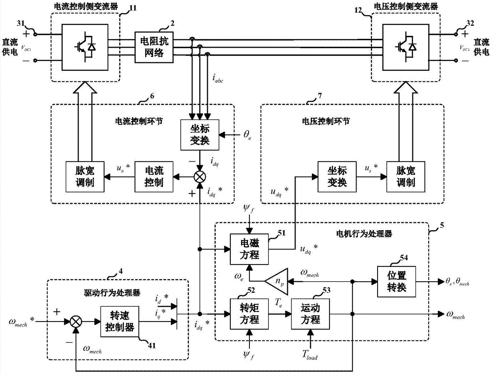
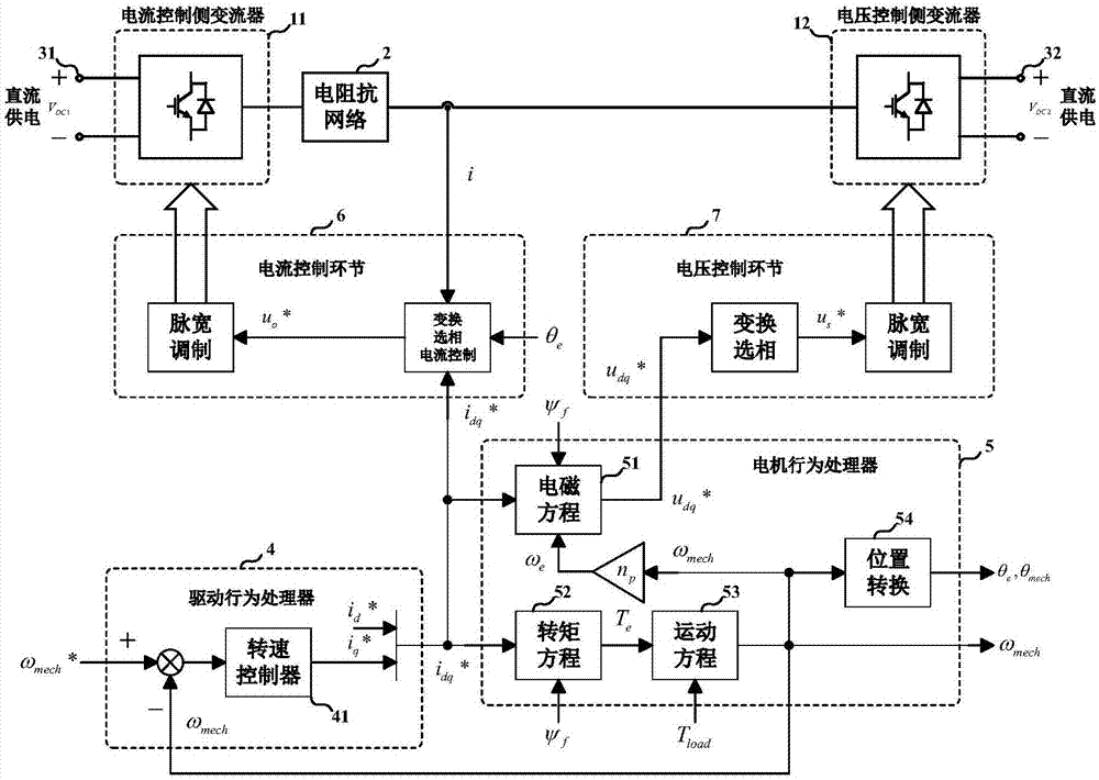
[0102] Specifically, such as figure 1 with figure 2 As shown in the embodiment, the voltage responsive permanent magnet synchronous motor and the simulator of its drive system provided by the present invention, its components include: current control side converter 11 and voltage control side converter 12, electrical impedance network 2 , DC power supply 3, drive behavior processor 4, motor behavior processor 5, current control link 6, voltage control link 7; wherein, figure 1 for a three-phase embod...


PUM


Abstract

The invention provides a voltage responding-type permanent magnet synchronous machine and a simulator of a driving system of the voltage responding-type permanent magnet synchronous machine. The voltage responding-type permanent magnet synchronous machine comprises at least two DC / AC power electronic converters, an electric impedance network, a direct current supply, a driving behavior processor,a motor behavior processor, a current control link and a voltage control link; the DC / AC power electronic converters are used for simulating the response of the driving system to incoming current of stator windings of the permanent magnet synchronous machine and the response of the permanent magnet synchronous machine to port voltage of stator current on a circuit layer separately; the driving behavior processor is used for describing electrical behavior characteristics of the driving system; the motor behavior processor is used for describing electrical and mechanical behavior features of thepermanent magnet synchronous machine. By means of the voltage responding-type permanent magnet synchronous machine, the response of the driving system to the incoming current of the stator windings of the permanent magnet synchronous machine and the response of the permanent magnet synchronous machine to the port voltage of the incoming current can be effectively simulated when the driving systemdrives the permanent magnet synchronous machine, full-electrification motor driving testing is achieved, and the testing efficiency and safety are improved.

Description

technical field [0001] The invention relates to the technical fields of power electronics and motors, in particular to a voltage-responsive permanent magnet synchronous motor and a simulator for its drive system. Background technique [0002] Permanent magnet synchronous motor (Permanent Magnet Synchronous Machine, PMSM) and its supporting drive system are widely used in wind power generation, industrial control, electric vehicles and other important fields of electric energy conversion and electric drive. In these applications, the power class and power density of permanent magnet synchronous motors are increasing, and the load characteristics are becoming more and more complex. During design, development and factory commissioning, it is often necessary to conduct a series of functional and reliability tests and verifications on the permanent magnet synchronous motor and its drive system. [0003] The traditional permanent magnet synchronous motor test method, in addition ...

Claims


Application Information

Patent Timeline
IPC IPC(8): H02P6/34H02P21/26H02P21/22H02P25/024H02P27/08
CPCH02P6/34H02P21/22H02P21/26H02P25/024H02P27/08H02P2207/05
Inventor 马柯宋宇博
Owner SHANGHAI JIAO TONG UNIV
Learn More