
Cleaning tool

A technology for cleaning tools and panels, which is applied in cleaning equipment, cleaning machinery, carpet cleaning, etc., and can solve problems such as throwing out, wiping cloth falling off, and low stability

Active Publication Date: 2018-05-08
HEBEI JIESHIBAO DAILY PLASTIC PROD CO LTD
View PDF10 Cites 13 Cited by
  • Summary
  • Abstract
  • Description
  • Claims
  • Application Information

AI Technical Summary

Problems solved by technology

The cleaning effect of this method is not good, and foreign matter such as hair wrapped around the cloth pan head is not easy to be thrown off the cloth pan head
Especially for the cloth pan head of the flat plate, since the cloth pan head is completely attached to the bottom surface of the flat plate, the centrifugal force generated when rotating and shaking is small, and it is difficult to throw out the foreign matter on the cloth pan head;
[0005] 2. The mop rod generally includes an upper connecting rod and a lower connecting rod sleeved in the upper connecting rod. In order to prevent the mop from being connected to the lower connecting rod during normal use For the relative sliding of the rods, a locking structure is often provided at the connection between the upper connecting rod and the lower connecting rod, but the locking structure in the prior art is more complicated and inconvenient to use
Chinese patent CN202568131U discloses "a telescopic mop rod". The fastening device adopts the cooperation of the handle and the elastic collar to loosen and clamp the sleeve rod by opening and closing the handle. The handle of the mop rod is hinged with the elastic collar , the handle is provided with a clip against the sleeve rod, and the elastic collar is provided with a gap for the clip to pass through. When the handle is closed, the clip presses against the sleeve rod to make it tightly connected with the elastic collar. The axial direction is perpendicular to the expansion and contraction direction of the sleeve rod, so when the mop rod is stressed, it will exert force on the clip. In order to prevent the clip from being forced to open the handle by mistake, the mop rod needs to be equipped with a positioning mechanism, that is, the arc on the elastic collar. The arc-shaped grooves and the arc-shaped protrusions on the handle that match the arc-shaped grooves have complex structures, cannot be fastened stably over time, and have a short service life;
[0006] 3. The mop rod and the mop disc mostly rotate 180°, that is, rotate back and forth or left and right, and the rotation method is not flexible, so it is not suitable for cleaning in a narrow range
Chinese patent "ZL201510439842.1" discloses "a universal mop head", which includes a connecting sleeve, a mop head body and a connecting ball, the first connecting column on the inner side of the lower end of the connecting sleeve and the front and rear sides of the connecting ball The first connection hole on the left and right sides of the connecting ball is connected by rotation, and the second connection column on the left and right sides of the connection ball is connected by rotation to the second connection hole on the top of the mop head body, thereby realizing a 360° rotation between the connection sleeve and the mop head body, but the first Rotating the connecting post and the second connecting post for a long time will cause the surface to be worn, resulting in low stability when fastened with the first connecting hole and the second connecting hole, thereby increasing the scrap rate of the product;
[0007] 4. The various parts of the mop tray are generally locked by screws and nuts. After the mop tray is assembled, it is not easy to disassemble, so it is difficult to clean the mop tray separately; In addition, since the mop disc is in direct contact with the ground during use, the mop disc is easily damaged due to impact, and any damage to any part of the mop disc in the prior art will cause the entire panel to be scrapped, thereby increasing the cost of use;
[0008]5. Since the two ends of the mop wiper are sleeved on the two ends of the bottom plate, long-term mopping and spin washing will cause the wiper to The two ends of the bottom plate fall off, affecting normal use

Method used


Image

  • Cleaning tool
  • Cleaning tool
  • Cleaning tool

Examples


Embodiment

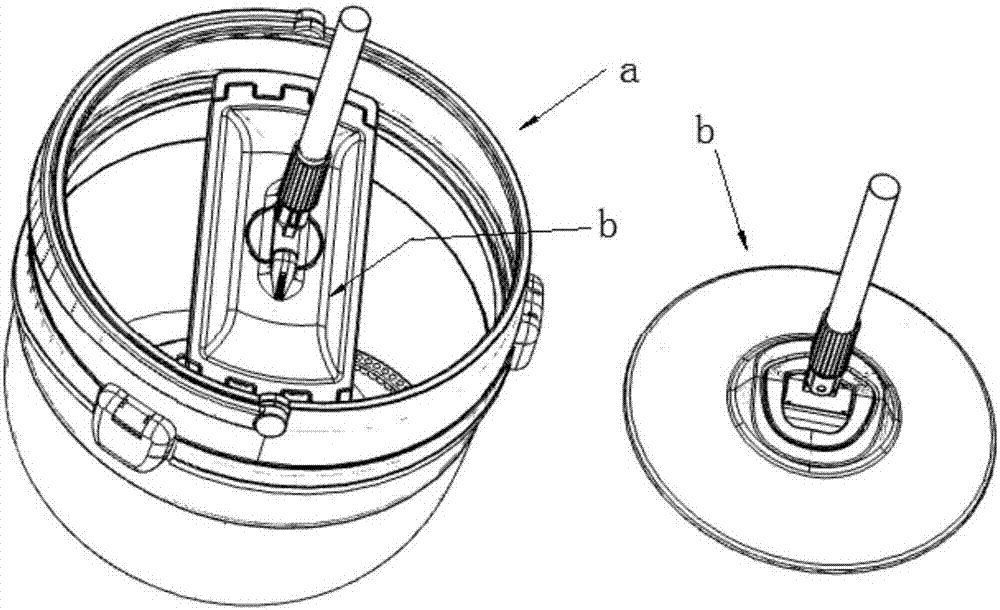
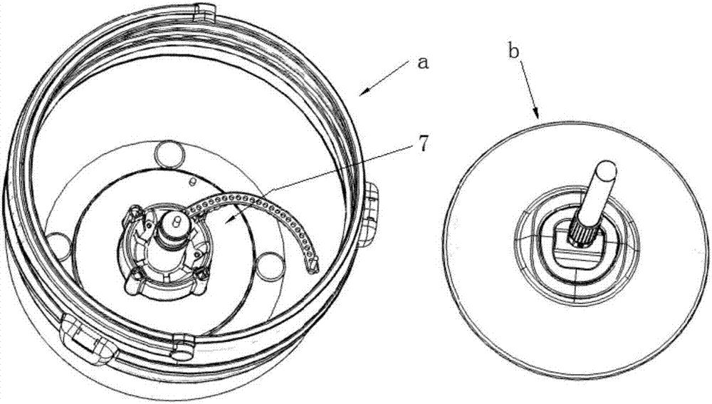
[0124] Embodiment: a kind of cleaning tool, as Figure 1-Figure 39 As shown, including mop bucket a and mop b;

[0125] The mop b includes a handle 5, a bottom plate and a rotating joint 4, the handle 5 includes an outer rod body 51 and an inner rod body 52, the outer rod body 51 and the inner rod body 52 are socketed, and the rotating joint includes a second A rotating member 41 and a second rotating member 42, the first rotating member 41 is rotatably connected to the second rotating member 42, the second rotating member 42 is rotatably connected to the connecting seat 3, and the first rotating member 42 is rotatably connected to the connecting seat 3. The rotating shaft of a rotating member 41 and the rotating shaft of the second rotating member 42 are perpendicular to each other, the first rotating member is connected to the handle, and the wiping cloth is located on the side of the bottom plate;

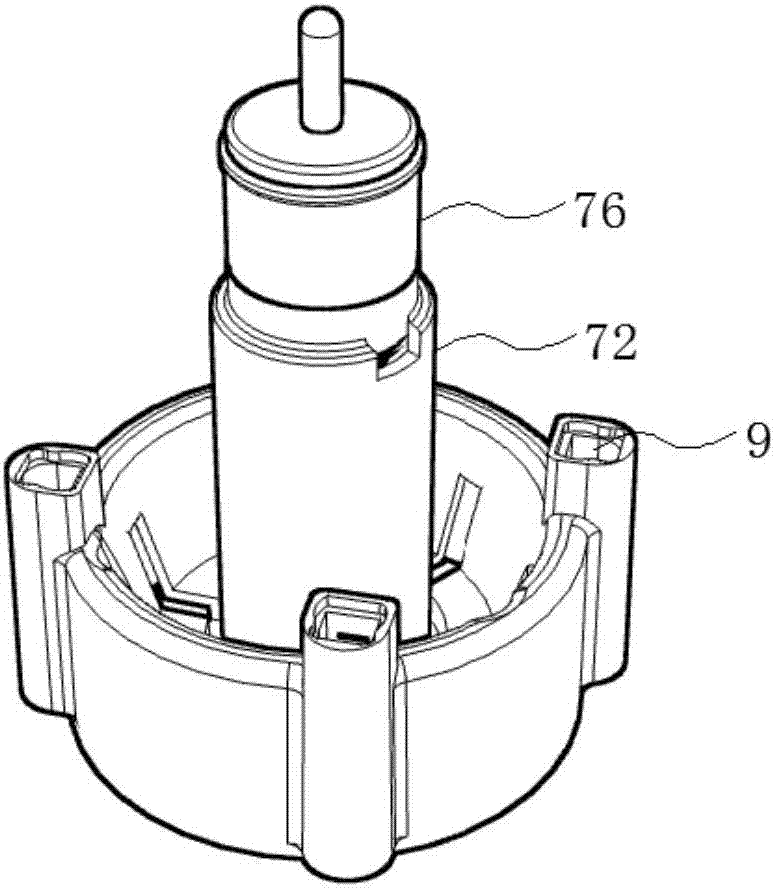
[0126] The bottom of the mop bucket a is provided with a lifting mechanism...


PUM


Abstract

The invention discloses a cleaning tool. The cleaning tool comprises a mop bucket and a mop. The mop comprises a mop rod, a bottom board and a rotation joint. The mop rod comprises an outer rod body and an inner rod body. The rotation joint comprises a first rotation part and a second rotation part. The bottom of the mop bucket is provided with a lifting mechanism. The lifting mechanism comprisesa fixing column fixed at the bottom of the mop bucket, a moving tube and a positioning rod. The moving tube is sheathed outside the fixing column. The positioning rod passes through the moving tube and is inserted in an inserting hole at the center of the fixing column, and the positioning rod is rotated relative to the fixing column. The lifting structure of the cleaning tool is simplified, and the operation is convenient, so the washing and dewatering functions of the mop are combined and coaxially performed, and the volume of the mop bucket can be reduced. The locking structure of the mop rod is simplified, and the angle between the mop rod and a faceplate can be conveniently adjusted and positioned. The locking structure is suitable for the mop or other cleaning tools with the similardemand. In addition, wiping cloth is effectively fixed on a bottom plate of the mop through a fixing claw by the lower faceplate, so the service life of the mop is prolonged.

Description

technical field [0001] The invention belongs to the technical field of cleaning products, in particular to a cleaning tool. Background technique [0002] At present, mop buckets with cleaning and dehydration functions are more popular on the market. Most of these mop buckets have a cleaning part and a dehydration part, and the cleaning part and the dehydration part are arranged side by side. Matching mop", the mop bucket is equipped with a cleaning part and a dehydration part, and a rotatable dehydration basket is provided in the dehydration part. ; The cleaning section is provided with a rotatable cleaning frame, and the cleaning frame is arranged at the bottom of the cleaning section, and the cleaning frame rotates under the drive of the rotating mop head. Drive it to rotate, and drive the water in the mop bucket to rotate together, so that the mop head is cleaned. [0003] There are following problems in the mop barrels currently on the market: [0004] 1. The mop buck...

Claims


Application Information

Patent Timeline
IPC IPC(8): A47L13/58
CPCA47L13/58
Inventor 任海燕
Owner HEBEI JIESHIBAO DAILY PLASTIC PROD CO LTD
Learn More