Outer circle grinding device for thin and long shaft workpiece

A technology of cylindrical grinding and slender shaft, which is applied in the direction of grinding drive device, machine tool designed for grinding the rotating surface of workpiece, grinding frame, etc. Problems such as machining accuracy and insufficiently compact fixing methods achieve the effect of fewer parts, low cost, and ingenious structural design.

Pending Publication Date: 2018-05-08
LUOYANG INST OF SCI & TECH
View PDF12 Cites 6 Cited by
  • Summary
  • Abstract
  • Description
  • Claims
  • Application Information

AI Technical Summary

Problems solved by technology

Using the traditional grinding device, the workpiece is easily bent and deformed under the action of radial grinding force, which affects the machining accuracy of the workpiece. Therefore, in order to solve the technical problems currently faced by the slender shaft workpiece and improve the processing quality, the cutting of the grinding wheel must be considered. Effect of force on workpiece with slender shaft
Secondly, the existing slender shaft grinding device fixes the workpiece only by two tops at the head and the tail to clamp the workpiece. Concave-convex on the outer surface of the shaft workpiece

Method used


Image

  • Outer circle grinding device for thin and long shaft workpiece
  • Outer circle grinding device for thin and long shaft workpiece
  • Outer circle grinding device for thin and long shaft workpiece

Examples


Embodiment Construction

[0016] In order to further explain the technical means and effects of the present invention to achieve the intended purpose of the invention, the following is a specific implementation of a cylindrical grinding device for a slender shaft workpiece according to the present invention in conjunction with the accompanying drawings and preferred embodiments Mode, structure, feature and effect thereof are as follows in detail.

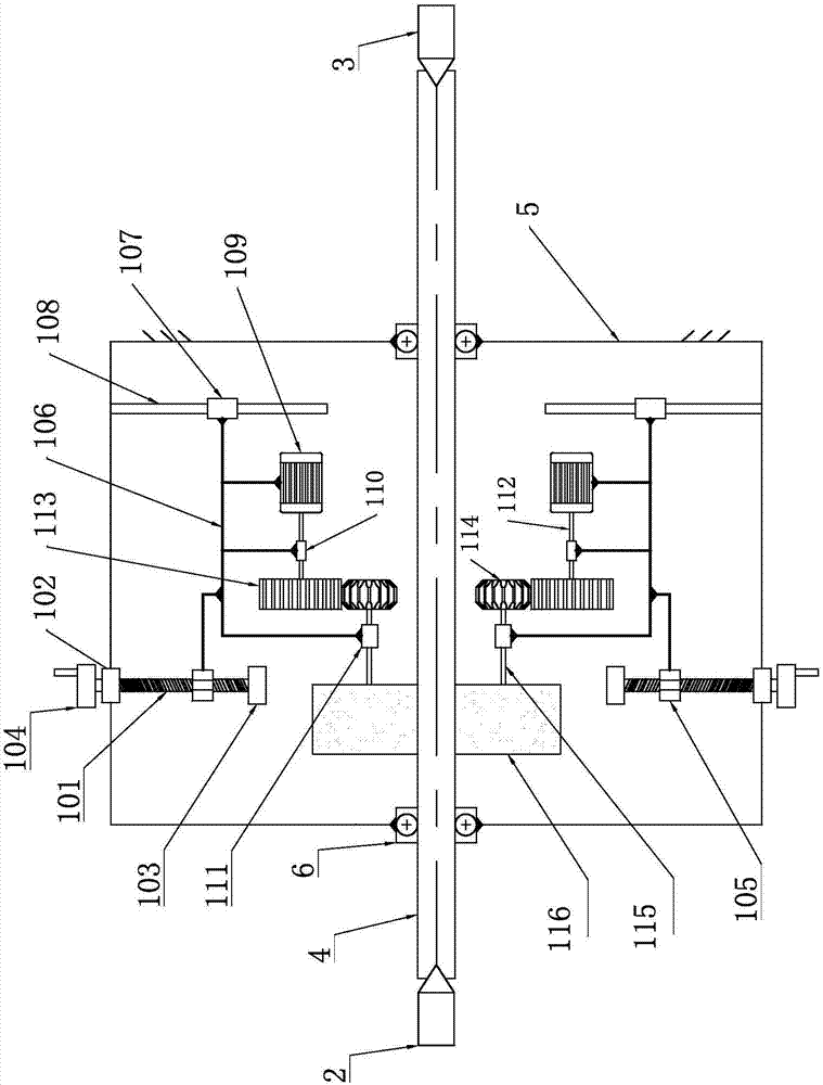
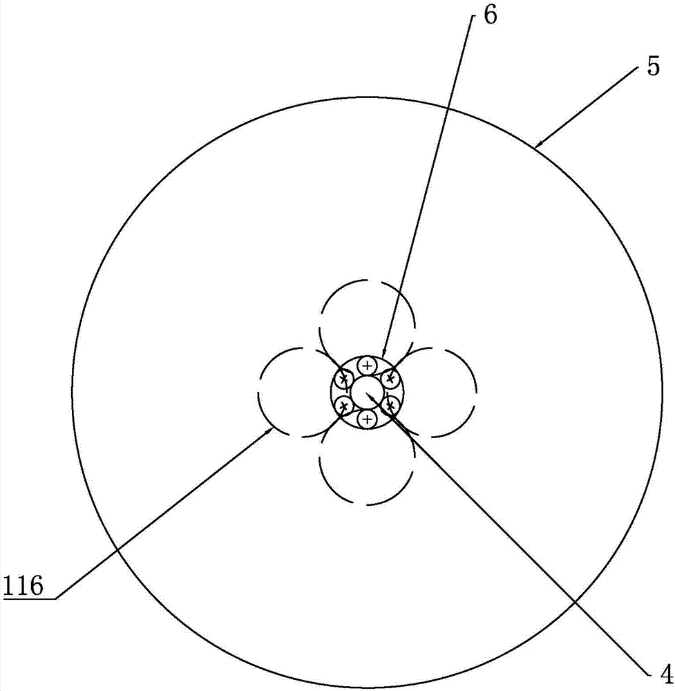
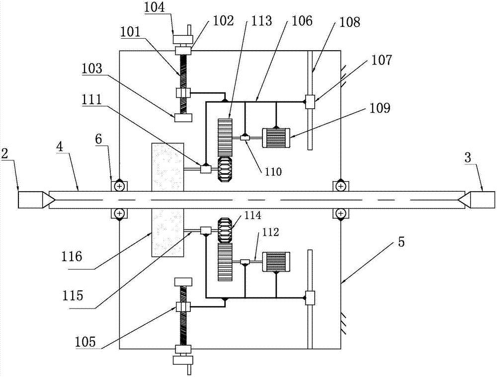
[0017] see Figure 1 to Figure 2 , a cylindrical grinding device for a slender shaft workpiece of the present invention, comprising a headstock top 2 and a tailstock top 3 for clamping a slender shaft workpiece, wherein the headstock top 2 is arranged on the headstock, and the tailstock The top 3 is arranged on the tailstock, and both the headstock and the tailstock are fixed on the workbench, and the workbench can slide on the grinding machine so as to realize the axial feeding of the slender shaft workpiece. The slender shaft workpiece 4 is set in the cas...


PUM


Abstract

An outer circle grinding device for a thin and long shaft workpiece comprises a head frame centre and a tail frame centre. The thin and long shaft workpiece is arranged between the head frame centre and the tail frame centre and arranged in a machine shell. A plurality of grinding mechanisms are arranged in the machine shell. Each grinding mechanism comprises a lead screw, wherein the two ends ofthe lead screw are arranged on a fixing base and a supporting base correspondingly, one end of the lead screw is connected with a hand wheel after stretching out of the fixing base, the lead screw isin screw joint with a nut, the nut is fixedly connected with a grinding wheel frame, the grinding wheel frame is fixedly connected with a sliding block, the sliding block is in sliding connection witha guide rail in the machine shell, the grinding wheel frame is further fixedly connected with a motor, an outer ring of a first bearing and an outer ring of a second bearing, the inner ring of the first bearing is connected with an output shaft of the motor, the output shaft is connected with a drive gear, the drive gear is engaged with a driven gear, and the driven gear is connected with a grinding wheel through a transmission rod. Grinding force of various grinding wheels to the thin and long shaft workpiece offset with one another, and the machining precision is improved; and a rolling guide rail is adopted for positioning, and the workpiece machining quality is guaranteed.

Description

technical field [0001] The invention belongs to the field of grinding devices for slender shaft workpieces, in particular to a cylindrical grinding device for slender shaft workpieces. Background technique [0002] Due to the small diameter and large length of the slender shaft workpiece, it has poor rigidity during grinding and is easily deformed under the action of grinding force. Using the traditional grinding device, the workpiece is easily bent and deformed under the action of radial grinding force, which affects the machining accuracy of the workpiece. Therefore, in order to solve the technical problems currently faced by the slender shaft workpiece and improve the processing quality, the cutting of the grinding wheel must be considered. The effect of force on workpieces with slender shafts. Secondly, the existing slender shaft grinding device fixes the workpiece only by two tops at the head and the tail to clamp the workpiece. Concave-convex on the outer surface of ...

Claims


Application Information

Patent Timeline
Patent Type & Authority Applications(China)
IPC IPC(8): B24B5/04B24B5/35B24B47/12B24B47/20B24B41/02B24B41/06
CPCB24B5/04B24B5/35B24B41/02B24B41/062B24B47/12B24B47/203
Inventor 常家东邹武岳遂录
Owner LUOYANG INST OF SCI & TECH
Why Eureka
Try Eureka