Framework for in-situ casting, preparation method and wall body made of framework

A skeleton and cast-in-place technology, applied to walls, building components, buildings, etc., can solve problems such as waste of energy, labor and water, and loss

Inactive Publication Date: 2018-05-08
李天昊
View PDF0 Cites 0 Cited by
  • Summary
  • Abstract
  • Description
  • Claims
  • Application Information

AI Technical Summary

Problems solved by technology

[0002] At present, the construction of cast-in-place frames and construction projects in our country adopts the formwork system to support cast-in-place. The above-mentioned pouring method has the following defects: First, there are many materials and accessories, such as all-steel formwork, steel-wood formwork, and multi-layer wood formwork. mold, plastic film, aluminum alloy mold, etc., and accessories include pull bolts, etc., before the construction period, according to the actual situation of the project, the materials used are complicated, the quantity is huge, the material consumption is large, the capital investment is large, and the cost is high; second, the construction process is complicated , the construction process increases, resulting in a large investment in human resources, high labor intensity, slow construction period, and high labor costs
Because concrete leakage is difficult to be effectively maintained in the natural environment, the strength of concrete is difficult to guarantee, and it is labor-intensive; third, most of the traditional external wall insulation is connected to the wall by sticking nails, and the surface is 3-6mm Thick mortar protective layer. Practice has proved that due to the influence of wind, sun, rain and other natural environments, the thermal insulation layer and protective layer in this technology generally crack and fall off in a short period of time, which affects the thermal insulation effect. and the service life, the insulation layer is mostly made of polystyrene board, which is a flammable material. During the construction period, the exposed

Method used


Image

  • Framework for in-situ casting, preparation method and wall body made of framework
  • Framework for in-situ casting, preparation method and wall body made of framework
  • Framework for in-situ casting, preparation method and wall body made of framework

Examples


Embodiment Construction

[0063] The structure and use principle of a cast-in-situ framework, a method for preparing a cast-in-situ framework, and a wall prepared by using a cast-in-situ framework of the present invention will be described in further detail below with reference to the drawings and specific embodiments.

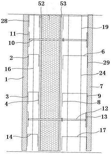
[0064] In order to express more clearly, the inside and outside described in the text are relative to the entire cast-in-place framework, that is, the side of a cast-in-place framework with the first membrane shell is defined as the outside, with the second membrane shell The side is defined as the inside.

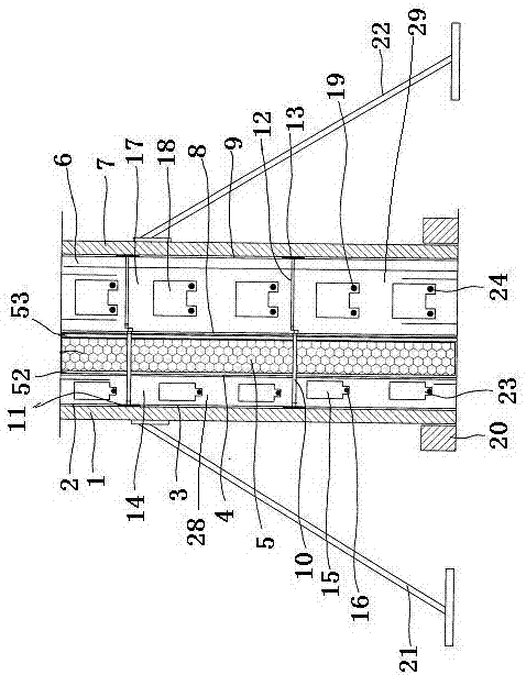
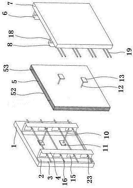
[0065] Such as figure 1 , figure 2 with image 3 As shown, a cast-in-situ skeleton of the present invention includes a first membrane shell 1 located at the outermost side. A first keel 2 containing at least two parallel bonding planes is provided on the inner side of the first membrane shell 1, and the first keel 2 is located The outer first bonding plane 3 is bonded to the inner surf...


PUM


Abstract

The invention belongs to the technical field of frameworks for in-situ casting, preparation methods of the frameworks, and buildings made of the frameworks, and discloses a framework for in-situ casting, a preparation method and a wall body made of the framework. The framework is characterized by comprising a first film shell located on the outermost side, and a first keel comprising at least twoparallel sticky planes is arranged on the inner side face of the first film shell; a second keel comprising at least two parallel sticky planes is arranged on the inner side of a heat-insulating board, and a second film shell is arranged on the inner side of the second keel; an inner pull rod and an outer pull rod which are mutually connected are arranged between the first film shell and the second film shell; fixed bases are arranged on the positions close to the lower portions of the outer sides of the first film shell and the second film shell, and a first supporting frame is arranged on the outer side face of the first film shell; and a second supporting frame is arranged on the inner side face of the second film shell. After supporting is completed, only direct casting is needed, machining and mounting are convenient, a large number of templates are saved, and the construction cost is greatly reduced; and after forming, the working procedures of wall plastering and concrete curingare omitted, the cost is saved, and production of building waste is reduced.

Description

Technical field [0001] The invention belongs to the technical field of a cast-in-place framework, a preparation method thereof and a building made of the framework, and in particular relates to a cast-in-place framework, a preparation method and a wall made of the framework. Background technique [0002] At present, the construction of cast-in-place frames and construction projects in China adopts the formwork system to support the cast-in-place. The use of the above-mentioned casting methods has the following defects: First, more materials and accessories are used, including all-steel molds, steel-wood molds, and multi-layer boards. Molds, plastic films, aluminum alloy molds, etc., and accessories such as tension bolts, etc. According to the actual situation of the project before the construction period, the materials used are complicated, the quantity is huge, the material consumption is large, the capital investment is large, and the cost is high; second, the construction proce...

Claims


Application Information

Patent Timeline
IPC IPC(8): E04B2/86
CPCE04B2/86E04B2/8635E04B2002/8688
Inventor 李天昊
Owner 李天昊
Why Eureka
Try Eureka