Capacitive liquid level detection method

A liquid level detection and capacitive technology, which is applied in the field of capacitive liquid level detection, can solve the problems of high production cost, inconvenient system maintenance and repair, and limited service life of reed switch, so as to reduce maintenance time cost and improve use economy performance, the effect of easy bonding resistance

Inactive Publication Date: 2018-05-08
四川泛华航空仪表电器有限公司
View PDF4 Cites 1 Cited by
  • Summary
  • Abstract
  • Description
  • Claims
  • Application Information

AI Technical Summary

Problems solved by technology

[0002] Sensor technology is the basic technology of the measurement control system. In the modern aircraft fuel measurement control system, various sensors are installed to measure various fuel properties and states, because the sensors are used in the fuel environment, and the entire measurement and control system It is very large and complex, which causes great inconvenience to the maintenance and repair of the system. Therefore, improving the service life and reliability of the products in the fuel tank is of great significance for improving the overall maintainability and economy of the aircraft.
The traditional aircraft fuel level annunciator adopts reed switch type annunciator or thermistor type annunciator. The two ends of the metal reed switch in the reed switch are attracted and closed, and then the alarm circuit is turned on. This kind of annunciator reed switch has limited service life, poor reliability, easy aging performance, complicated manufacturing process, high production cost, and easy Affected by other electromagnetic equipment in the fuel tank, such as solenoid valves or fuel pumps, there are relatively strict requirements for the installation location of the equipment; while the thermistor type annunciator needs an external circuit to heat the thermistor in the annunciator. It is easy to cause heat accumulation in the tank and even cause the temperature of the annunciator to exceed the fuel flash point and cause a catastrophic accident, so it has rarely been used in recent aircraft

Method used


Image

  • Capacitive liquid level detection method
  • Capacitive liquid level detection method

Examples


Embodiment 1

[0019] A capacitive liquid level detection method in this embodiment, a capacitive liquid level detection method, uses liquid to fill a capacitive signal device composed of polar tubes to change the capacitance value of the capacitive signal device, and then the capacitance Value changes to determine the liquid level.

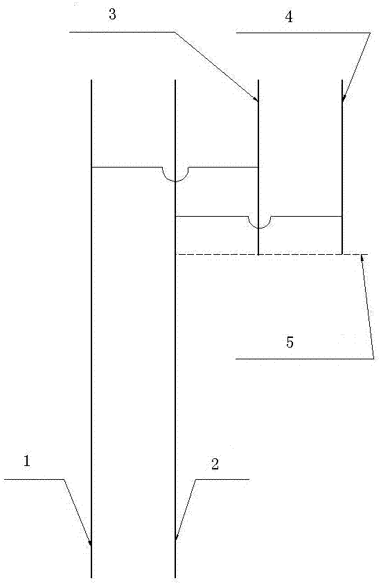
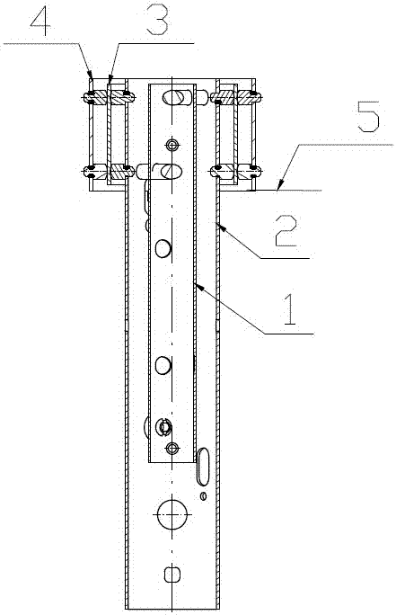
[0020] Such as figure 1 with figure 2 As shown: the capacitive annunciator includes a capacitive tube body and a signal prompter electrically connected to the capacitive tube body, and the capacitive tube body includes an inner tube 1, an outer tube 2, and an inner signal tube 3 that are sequentially set from the inside to the outside , the outer signal tube 4; the inner tube 1 is electrically connected to the inner signal tube 3 to form a capacitor N pole, and the outer tube 2 and the outer signal tube 4 are electrically connected to form a capacitor P pole; the inner signal tube 3 Consistent with the length of the outer signal tube 4, the length of the inn...

Embodiment 2

[0022] This embodiment is further optimized on the basis of Embodiment 1. The liquid level detection method of the capacitor composed of polar tubes specifically includes the following steps:

[0023] Step S1: Connect the inner signal tube 3 and the inner tube 1 together with wires to form one pole of the capacitor together as N pole; connect the outer signal tube 4 and the outer tube 2 together with wires to form the other pole of the capacitor together The pole is recorded as P pole.

[0024] Step S2: When the capacitive annunciator is used as a low fuel level alarm annunciator, fix the bottom of the inner tube 1 and outer tube 2 to the bottom of the fuel tank. The initial state is that the four-layer tube of the annunciator is filled with fuel. When it gradually decreases, because the dielectric constant of fuel is greater than that of air, the capacitance value between the P pole and N pole decreases proportionally with the decrease of the liquid level. When the liquid lev...

Embodiment 3

[0029]A capacitive liquid level detection method in this embodiment uses liquid to fill a capacitive annunciator composed of polar tubes to change the capacitance value in the capacitive annunciator, and then judge the liquid level by the change of capacitance value. liquid level. Among them, the capacitive signal device includes a signal prompter with a capacitor tube body electrically connected to the capacitor tube body. The capacitor tube body includes an inner tube 1, an outer tube 2, an inner signal tube 3, and an outer signal tube that are sequentially set from inside to outside. Tube 4; the inner tube 1 is electrically connected to the inner signal tube 3 to form a capacitor N pole, and the outer tube 2 and the outer signal tube 4 are electrically connected to form a capacitor P pole; the inner signal tube 3 and the outer signal tube The tubes 4 have the same length, the inner tube 1 and the outer tube 2 have the same length, and the inner tube 1 is longer than the inn...


PUM


Abstract

The invention discloses a capacitive liquid level detection method. A capacitive annunciator formed by a polarity pipe is filled by liquid, to change capacitance value of the capacitive annunciator, so as to determine liquid level of liquid through variation conditions of the capacitance values. The capacitive annunciator is a variable capacitive sensor formed by four layers of pipes. On a warningsignal point, the capacitance value of the annunciator has a high jump, so that a fuel oil liquid level reaches the warning signal point position is determined. When the liquid level annunciator is arranged close to the bottom of a fuel tank, the liquid level annunciator can be used to detect whether oil level is below a warning oil level. When the liquid level annunciator is arranged close to the top of the fuel tank, the liquid level annunciator can be used to detect whether the oil level reaches a full state. Compared with a conventional reed switch annunciator and a thermistor annunciator, the capacitive annunciator does not have movable components, so reliability and service life are greatly improved. The capacitive annunciator is simple and reliable in structure, higher in security,and lower in production cost, and maintainability is greatly improved.

Description

technical field [0001] The invention relates to the field of liquid level detection, in particular to a capacitive liquid level detection method. Background technique [0002] Sensor technology is the basic technology of the measurement control system. In the modern aircraft fuel measurement control system, various sensors are installed to measure various fuel properties and states, because the sensors are used in the fuel environment, and the entire measurement and control system It is very large and complex, which causes great inconvenience to the maintenance and repair of the system. Therefore, improving the service life and reliability of the products in the fuel tank is of great significance for improving the overall maintainability and economy of the aircraft. The traditional aircraft fuel level annunciator adopts reed switch type annunciator or thermistor type annunciator. The two ends of the metal reed switch in the reed switch are attracted and closed, and then the...

Claims


Application Information

Patent Timeline
Patent Type & Authority Applications(China)
IPC IPC(8): G01F23/26
CPCG01F23/265
Inventor 牛满江杨光明师显强
Owner 四川泛华航空仪表电器有限公司
Why Eureka
Try Eureka