Self-energy feeding type brake device for airplanes

A braking device and self-feeding energy technology, applied in the direction of aircraft braking arrangement, can solve the problems of volume, heat dissipation and reliability, high power density, heavy motor load, etc., and achieve easy thermal balance design, high reliability and high reliability. Maintainability and weight reduction effect

Active Publication Date: 2012-12-19
BEIHANG UNIV
View PDF6 Cites 0 Cited by
  • Summary
  • Abstract
  • Description
  • Claims
  • Application Information

AI Technical Summary

Problems solved by technology

However, because of the high power and amazing power density, the burden on the motor is very heavy, and the problems of volume, heat dissipation and reliability are particularly difficult. It is often necessary to return the cooling device of the motor to the landing gear compartment, or arrange the pump and the motor in the undercarriage. In the landing gear cabin, annoying pipelines are still needed. Compared with hydraulic brakes, it only saves the connection pipeline between the brake system and the main hydraulic source of the aircraft, which is not thorough enough.

Method used


Image

  • Self-energy feeding type brake device for airplanes
  • Self-energy feeding type brake device for airplanes

Examples


Embodiment

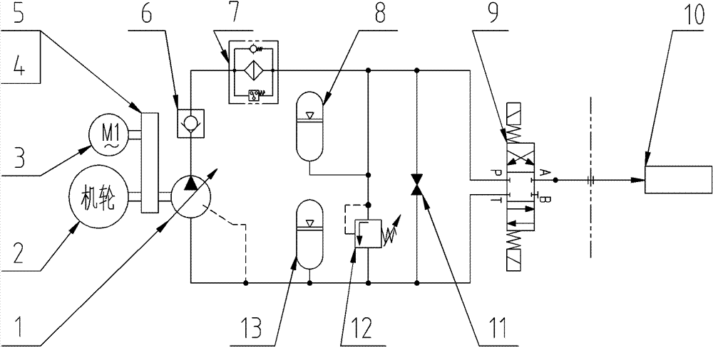
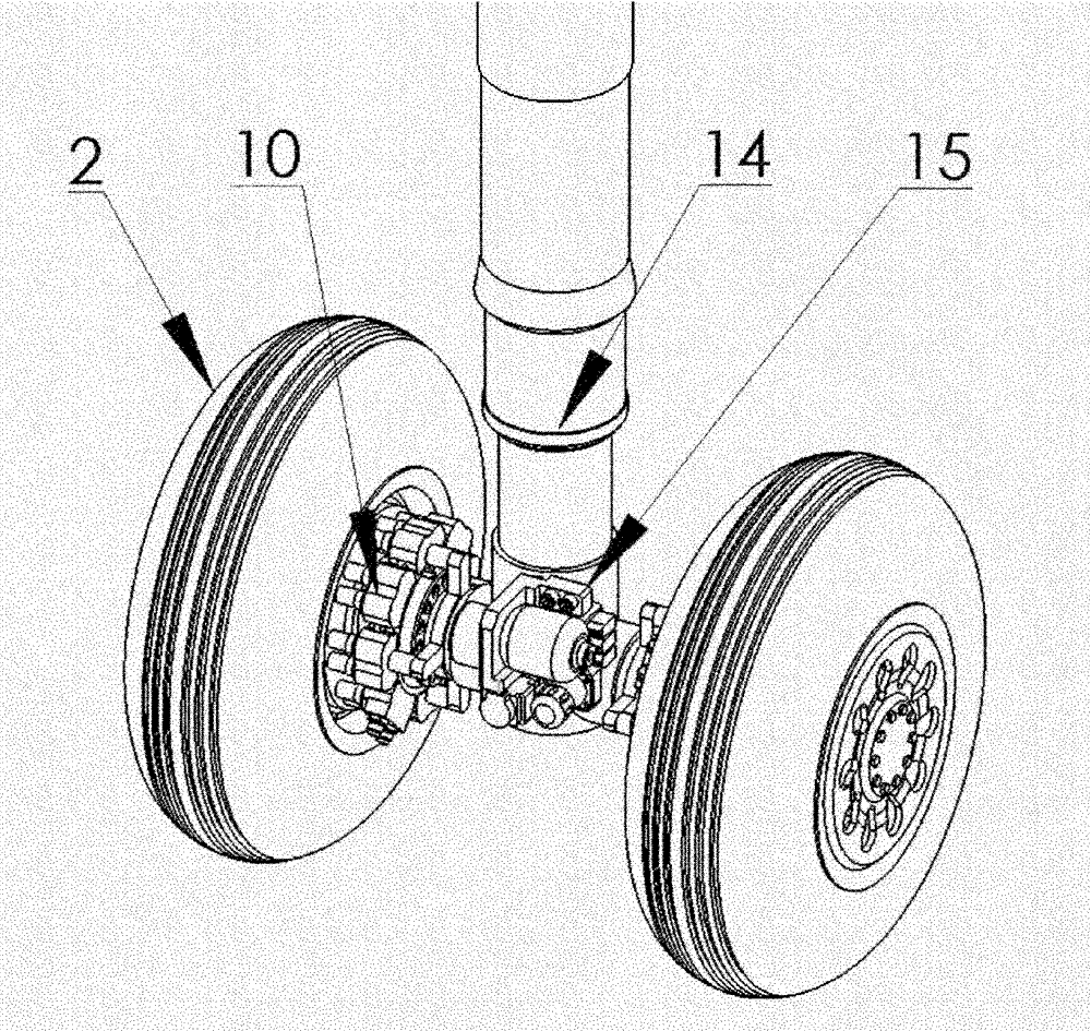
[0030] like figure 2 As shown, it is a schematic diagram of the actual installation of the aircraft self-feeding brake device according to the present invention. The hydraulic pump 1 adopts a constant pressure variable pump, and the input shaft of the constant pressure variable pump passes through the reducer 4 and the clutch 5 and then connects with the wheel 2 through gears. , The accumulator 8 adopts a diaphragm accumulator, and the fuel tank 13 adopts a pressurized fuel tank. The aircraft self-feeding brake device 15 is provided with an integrated integrated block, and all components (including hydraulic pump 1, auxiliary motor 3, speed reducer 4, electromagnetic clutch 5, check valve 6, high-pressure oil filter 7, accumulator 8, brake valve 9, bypass valve 11, overflow valve 12 and fuel tank 13) are all installed on the integrated block, self-feeding brake device 15 is installed on the aircraft landing gear 14, when the aircraft lands, the aircraft wheel 2 starts When i...


PUM


Abstract

The invention discloses a self-energy feeding type brake device for airplanes, belonging to the technical field of an airplane brake system, comprising a hydraulic pump, an auxiliary motor, a reducer, an electromagnetic clutch, a one-way valve, a high pressure oil filter, an energy accumulator, a brake valve, a by-pass valve, an overflow valve and an oil tank, wherein an input shaft of the hydraulic pump is connected with wheel shafts of airplane wheels via the electromagnetic clutch and the reducer; the electromagnetic clutch and the reducer are connected with the auxiliary motor; an oil suction port of the hydraulic pump is connected with the oil tank; an oil outlet of the hydraulic pump is sequentially connected with the one-way valve and the high pressure oil filter; then the oil passage is divided into three parallel branch oil passages; the first branch oil passage is sequentially connected with the energy accumulator and the overflow valve; the second branch oil passage is connected with the by-pass valve; the third branch oil passage is connected with a brake pressure servo valve; the three branch oil passages are gathered to enter into the oil tank; and the brake valve isconnected with a brake actuator via the oil passage. The brake device adopts an integral structure design and electrical interfaces, and directly converts the energy after the airplane lands into theenergy needed by the brake device for anti-skidding braking.

Description

technical field [0001] The invention belongs to the technical field of aircraft braking systems, and in particular relates to an aircraft self-feeding type braking device. Background technique [0002] The aircraft braking system is an important airborne equipment, which plays a vital role in the normal take-off and landing of the aircraft. The performance quality of the braking system determines the safety of the aircraft and the crew on board. The current braking system is divided into two types: hydraulic braking system and electric braking system. [0003] At present, hydraulic power is still widely used in aircraft brake systems in the world. The energy of the system is supplied by multiple sets of centralized pump sources onboard, consumes the power of the aircraft's hydraulic system, and is transmitted to the braking devices distributed on each main wheel through pipelines, and redundancy technology is usually used. The advantages of the traditional hydraulic brake ...

Claims


Application Information

Patent Timeline
Patent Type & Authority Patents(China)
IPC IPC(8): B64C25/42
Inventor 焦宗夏黄澄尚耀星李丰羽
Owner BEIHANG UNIV
Why Eureka
Try Eureka