

Dynamic comparator and method of imbalance calibration thereof
A dynamic comparator and calibration control technology, applied in the communication field, can solve the problems of increased calibration time and high power consumption cost, and achieve the effects of improving conversion accuracy, low power consumption cost, and eliminating offset
- Summary
- Abstract
- Description
- Claims
- Application Information
AI Technical Summary
Problems solved by technology
Method used
Image

Examples
Embodiment 1
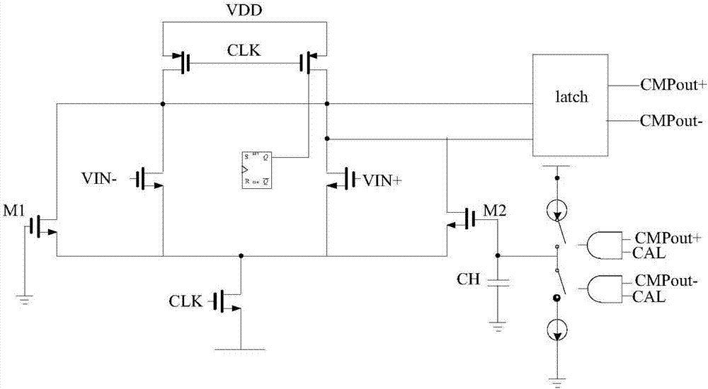
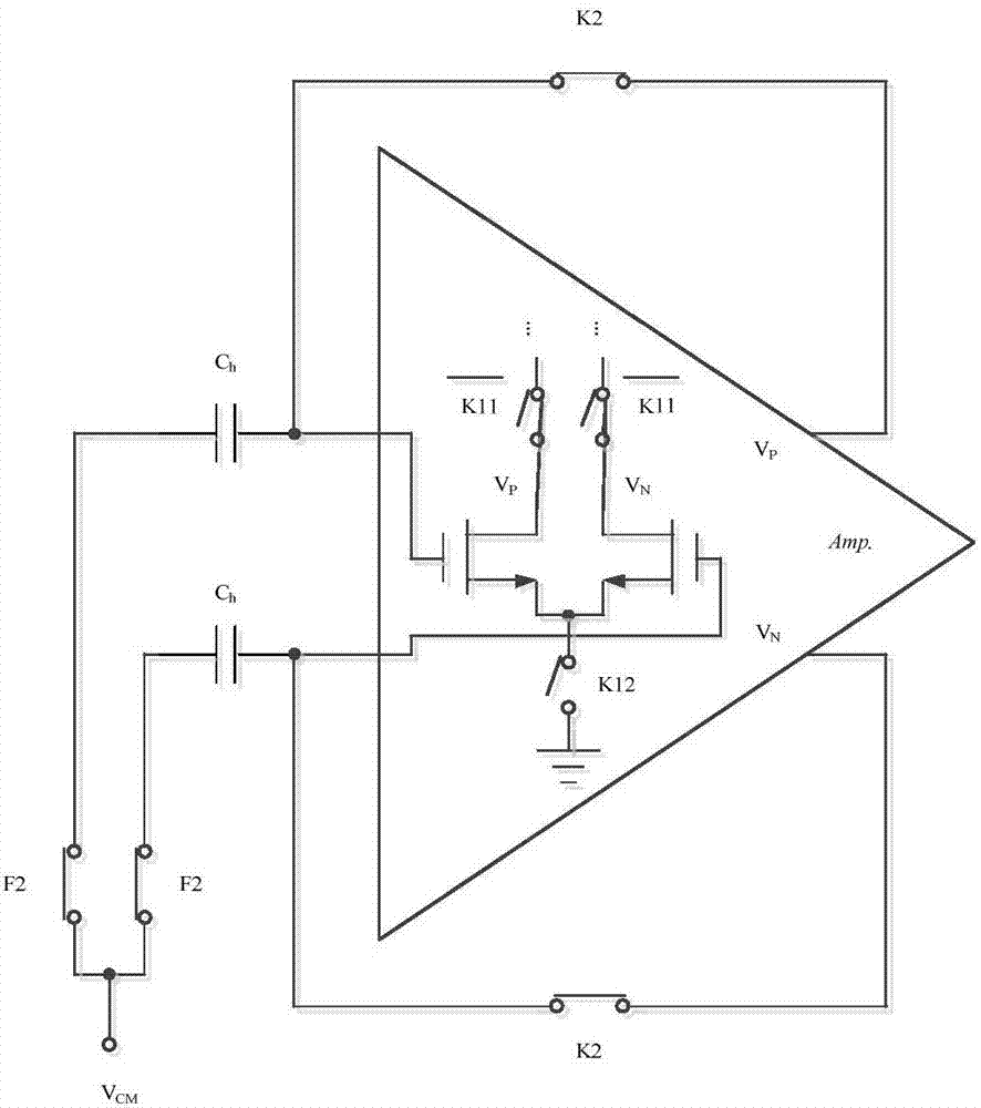
[0052] The first embodiment of the present invention provides a dynamic comparator, such as image 3 As shown, the dynamic comparator includes a latch and a pre-amplifier including a pre-amplification circuit and a calibration auxiliary circuit; the calibration auxiliary circuit includes a charge storage capacitor Ch for storing an offset voltage, a charge and discharge switch K2, and a common mode switch F2 , The first calibration control switch K11 and the second calibration control switch K12; the gate of the input differential NMOS tube of the pre-amplification circuit is connected to the first end of the charge storage capacitor Ch and the first end of the charge and discharge switch K2, respectively, The second end of the storage capacitor Ch is respectively connected to the first end of the common mode switch F2 and the input end of the dynamic comparator, and the second end of the common mode switch F2 is connected to the input common mode voltage power supply V of the pr...
Embodiment 2
[0068] In the embodiment of the invention, combining Figure 3 to Figure 6 The shown dynamic comparator describes the method of offset calibration of the dynamic comparator provided by the embodiment of the present invention, such as Figure 7 As shown, the method includes:
[0069] S701. In the offset calibration state, turn on the first calibration control switch, turn off the second calibration control switch, the common mode switch, and the charge and discharge switch respectively, and set the calibration voltage of the pre-amplification circuit The power supply charges the input differential NMOS tube so that the voltage value of the drain of the input differential NMOS tube reaches the calibration voltage;
[0070] S702. Turn off the first calibration control switch, turn on the second calibration control switch, the common mode switch, and the charge-discharge switch, respectively, and the drain voltage of the input differential NMOS transistor passes through the The input d...
Embodiment 3
[0078] In this embodiment, combining Figure 8 (A), Figure 8 (B), Picture 9 (A), Picture 9 (B) Provided for the embodiments of the present invention Figure 3-Figure 6 The offset calibration method of the dynamic comparator shown is explained.
[0079] It should be noted that in the pre-amplifier part, the input differential pair tubes M1 and M2, the first comparison control switch F1K1, the second comparison control switch F1K2 and the differential input switch F1 constitute the normal pre-amplification circuit of the comparator, and the input of the pre-amplification circuit The charge storage capacitor Ch, the first calibration control switch K11, the second calibration control switch K12, the charge and discharge switch K2 and the common mode switch F2 connected in series with the terminals constitute the calibration auxiliary circuit of the comparator. The comparator is divided into two stages: offset storage (offset calibration state) and normal comparison (comparison sta...
PUM
 Abstract
Description
Claims
Application Information