
Frequency conversion compensating microwave frequency transmission system and method

A technology of microwave frequency and transmission system, which is applied in the direction of electromagnetic wave transmission system, transmission system, digital transmission system, etc., can solve problems such as different operating frequencies and weak signal interference, and achieve the goal of improving stability, avoiding phase interference, and avoiding signal interference Effect

Active Publication Date: 2018-05-08
NAT TIME SERVICE CENT CHINESE ACAD OF SCI
View PDF7 Cites 32 Cited by
  • Summary
  • Abstract
  • Description
  • Claims
  • Application Information

AI Technical Summary

Problems solved by technology

The present invention makes use of frequency converters to make the operating frequencies of the local and remote sites different, and can solve the problem that the strong signal in the site interferes with the weak signal received by detection

Method used


Image

  • Frequency conversion compensating microwave frequency transmission system and method
  • Frequency conversion compensating microwave frequency transmission system and method
  • Frequency conversion compensating microwave frequency transmission system and method

Examples


Embodiment Construction

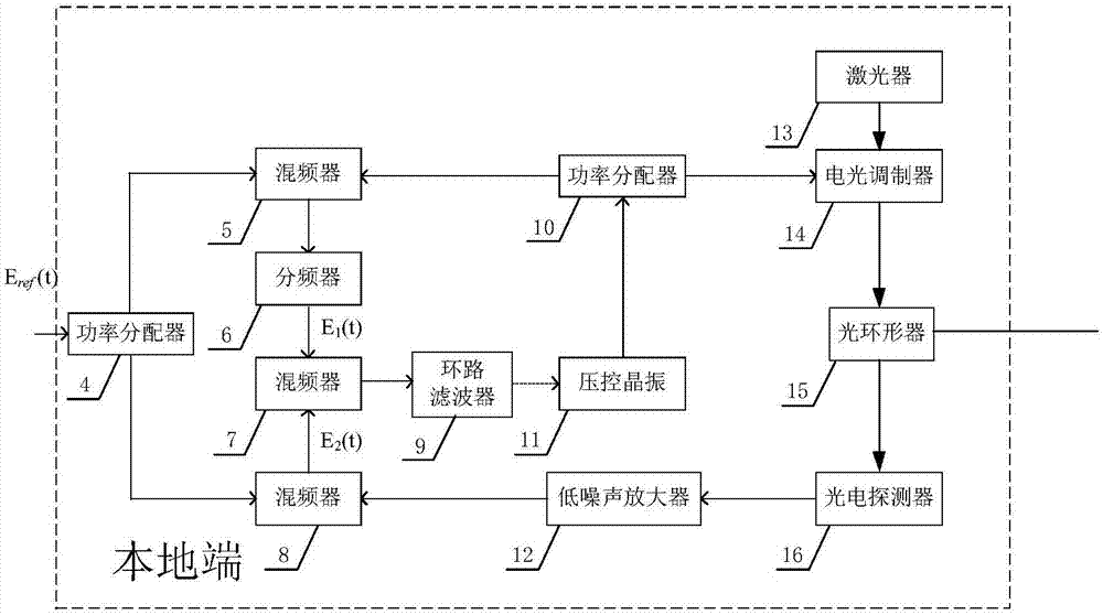
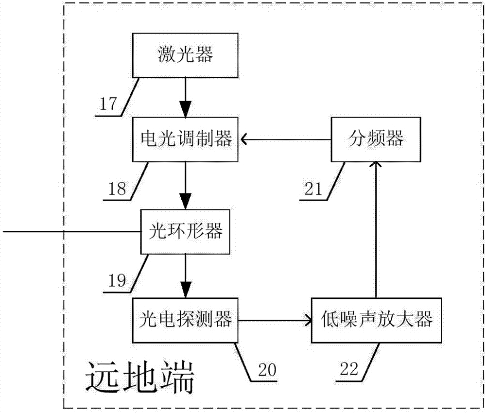
[0026] see figure 1 As shown, a frequency conversion compensation microwave frequency transmission system of the present invention includes: a local terminal 1 , an optical fiber link 2 and a remote terminal 3 . The local end 1 and the remote end 3 are connected through an optical fiber link 2 .

[0027] see figure 2 As shown, the local terminal 1 includes a first power splitter 4, a first mixer 5, a first frequency divider 6, a second mixer 7, a third mixer 8, a loop filter 9, a second A power divider 10 , a voltage-controlled crystal oscillator 11 , a first low-noise amplifier 12 , a local-end laser 13 , a first electro-optic modulator 14 , a first optical circulator 15 and a first photodetector 16 .

[0028] The output end of the local end laser 13 is connected to the optical input port of the first electro-optic modulator 14, the optical output port of the first electro-optic modulator 14 is connected to the first port of the first optical circulator 15, and the second ...


PUM


Abstract

The invention discloses a frequency conversion compensating microwave frequency transmission system and method. A phase pre-compensated microwave transmission signal is loaded into a laser signal, thelaser signal is transmitted to a remote end through utilization of an optical fiber, and the remote end restores the laser signal into a frequency signal synchronous with a microwave reference frequency signal of a local end through detection. According to a specific process, after a local signal is transmitted to the remote end, frequency conversion is carried out on a detection signal of the remote end, the detection signal is returned to the local end, a return signal comprises phase noise imported into an optical fiber link; the return signal and the local transmission signal are respectively mixed with the local reference signal, comparison is carried out to acquire pre-compensation quantity and a crystal oscillator generating the transmission signal is controlled according to the compensation quantity, so phase compensation of high precision frequency transmission is finished. Compared with existing frequency transmission, the method mainly has the advantages that frequencies ofthe signals transmitted by the local end and returned by the remote end are different, the phase interference of strong signals of stations at the two ends for detected and received weak signals is avoided, and the frequency transmission stability is further improved.

Description

technical field [0001] The invention relates to the technical field of optical fiber time-frequency transmission, in particular to a frequency conversion compensation microwave frequency transmission system and method. Background technique [0002] There are many ways to transmit frequency standards. The traditional frequency transmission methods are mainly free space propagation, including short-wave timing, long-wave timing, and GPS. Optical fiber frequency transmission is an emerging high-precision frequency signal transmission technology based on optical fiber. This technology uses communication optical fiber as the transmission channel of frequency signals, and can transmit various time and frequency signals such as time, microwave frequency and optical frequency. It has high precision, With the advantages of low noise, low loss, rich channel resources, etc., the stability of frequency transmission is far superior to the widely used satellite timing technology at presen...

Claims


Application Information

Patent Timeline
IPC IPC(8): H04B10/2507H04B10/2575H04B10/50H04B10/69H04L7/00
CPCH04B10/2507H04B10/2575H04B10/50577H04B10/697H04L7/0075
Inventor 赵文宇姜海峰赵粹臣闫露露张首刚
Owner NAT TIME SERVICE CENT CHINESE ACAD OF SCI
Learn More