Centrifugal fan for hot draw box

A centrifugal fan and heat box technology, applied in the direction of mechanical equipment, machines/engines, liquid fuel engines, etc., can solve the problems of the interference of the working environment of the staff, the loud noise of the centrifugal fan, and the easy slipping and loosening of the transmission wheel, so as to avoid It is difficult to rotate, avoid slipping and loosening, and the effect of firm and tight connection

Inactive Publication Date: 2018-05-11
JIANGSU HENGKANG ELECTRICAL
View PDF0 Cites 0 Cited by
  • Summary
  • Abstract
  • Description
  • Claims
  • Application Information

AI Technical Summary

Problems solved by technology

[0002] The centrifugal fan is a machine that increases the gas pressure through mechanical energy, and then transports the gas out. The centrifugal fan for the drafting hot box is a device that is applied to the drafting hot box to transport cold and hot air; the existing There are certain disadvantages in the use of the centrifugal fan for the drafting hot box. The motor shaft of the centrifugal fan is prone to rust and corrosion after long-term use, which makes it difficult to rotate the shaft. The working environment of the staff causes interference, and the transmission wheel of the centrifugal fan is easy to slip and loose during the transmission process, and the transmission effect is poor, which brings a certain impact during use. Therefore, we propose a drafting hot box. Centrifugal Fan

Method used


Image

  • Centrifugal fan for hot draw box
  • Centrifugal fan for hot draw box
  • Centrifugal fan for hot draw box

Examples


Embodiment Construction

[0016] In order to make the technical means, creative features, goals and effects achieved by the present invention easy to understand, the present invention will be further described below in conjunction with specific embodiments.

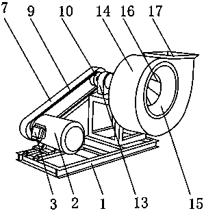
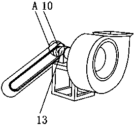
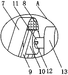
[0017] Such as Figure 1-4 As shown, a centrifugal fan for a drafting hot box includes a base 1, a motor 2 is fixedly installed on the outer surface of the upper end of the base 1, a junction box 3 is fixedly installed on one side of the outer surface of the motor 2, and a junction box 3 is fixedly installed on the outer surface of one end of the motor 2. Fixedly connected with a rotating shaft 4, one end of the rotating shaft 4 is fixedly mounted with a runner 5, the outer surface of the rotating shaft 4 is provided with an oil groove 6 near the runner 5, and one end of the oil groove 6 extends into the inside of the runner 5, when using lubricating oil When lubricating, lubricating oil can flow into the connection between the runner 5 and the ro...


PUM


Abstract

The invention discloses a centrifugal fan for a hot draw box. The centrifugal fan comprises a base, wherein a motor is fixedly arranged on the outer surface at the upper end of the base; a junction box is fixedly arranged on the outer surface of one side of the motor; a rotating shaft is fixedly connected onto the outer surface of one end of the motor; a runner is fixedly arranged at one end of the rotating shaft; an oil groove is formed in a position, which is close to the runner, of the outer surface of the rotating shaft; a protective cover is fixedly arranged at a position, which is positioned above the base, of one side of the motor; a foam board is arranged on the inner surface of the protective cover; a transmission belt is arranged at a position, which is positioned on one side ofthe motor, of the interior of the protective cover; and a transmission wheel is arranged at a position, which is positioned inside the protective cover, of one end of the transmission belt. The centrifugal fan for the hot draw box, disclosed by the invention, is provided with the oil groove, the foam board and end links, so that the rotating shaft of the motor can be conveniently lubricated, noisepollution can be reduced, and loose joint of the transmission wheel can be avoided. The centrifugal fan is applicable to different operations and brings excellent application prospects.

Description

technical field [0001] The invention belongs to the field of ventilators, in particular to a centrifugal ventilator for a drafting hot box. Background technique [0002] The centrifugal fan is a machine that increases the gas pressure through mechanical energy, and then transports the gas out. The centrifugal fan for the drafting hot box is a device that is applied to the drafting hot box to transport cold and hot air; the existing There are certain disadvantages in the use of the centrifugal fan for the drafting hot box. The motor shaft of the centrifugal fan is prone to rust and corrosion after long-term use, which makes it difficult to rotate the shaft. The working environment of the staff causes interference, and the transmission wheel of the centrifugal fan is easy to slip and loose during the transmission process, and the transmission effect is poor, which brings a certain impact during use. Therefore, we propose a drafting hot box. Centrifugal Fan. Contents of the ...

Claims


Application Information

Patent Timeline
Patent Type & Authority Applications(China)
IPC IPC(8): F04D25/08F04D29/66F04D29/063F16H7/20F16H57/00F16H57/04
CPCF04D25/08F04D29/063F04D29/664F16H7/20F16H57/0025F16H57/043
Inventor 孙勇安刘万勤刘正东孙健
Owner JIANGSU HENGKANG ELECTRICAL
Why Eureka
Try Eureka