A method for detecting the manufacturing quality of aircraft surface based on 3D data

A technology of manufacturing quality and detection methods, which is applied in the direction of instruments, measuring devices, and optical devices, etc., can solve problems such as unsuitable for aircraft surface manufacturing quality inspection, information error flooding of rivet interest areas, and waste of time

Active Publication Date: 2019-07-02
SHENYANG INST OF AUTOMATION - CHINESE ACAD OF SCI
View PDF4 Cites 0 Cited by
  • Summary
  • Abstract
  • Description
  • Claims
  • Application Information

AI Technical Summary

Problems solved by technology

Due to the large scale of the aircraft, there is currently no effective method for high-precision and large-scale measurement modeling of the entire aircraft shape. Requires massive calculations, and it is difficult for ordinary computers to complete
Furthermore, the slight deviation of the 3D design model has a huge impact on the detection results
If it is further considered that the surface of the aircraft skin has a large shape and position tolerance, the difference between the design model and the scanning model may be far greater than the scale of the surface rivet ROI, resulting in the information of the rivet ROI being overwhelmed by errors
[0004] Therefore, the existing 3D rivet ROI detection method is not suitable for aircraft surface manufacturing quality inspection
In addition, during the actual detection and maintenance of the surface rivet ROI, the measurement results are generally displayed on the computer screen. When marking and repairing the rivet ROI, the operator needs to check and walk back and forth between the screen and the target, or through Others establish relay communication, which is a waste of time and easily introduces process errors

Method used


Image

  • A method for detecting the manufacturing quality of aircraft surface based on 3D data
  • A method for detecting the manufacturing quality of aircraft surface based on 3D data
  • A method for detecting the manufacturing quality of aircraft surface based on 3D data

Examples


Embodiment Construction

[0079] The present invention will be further described in detail below in conjunction with the accompanying drawings and embodiments.

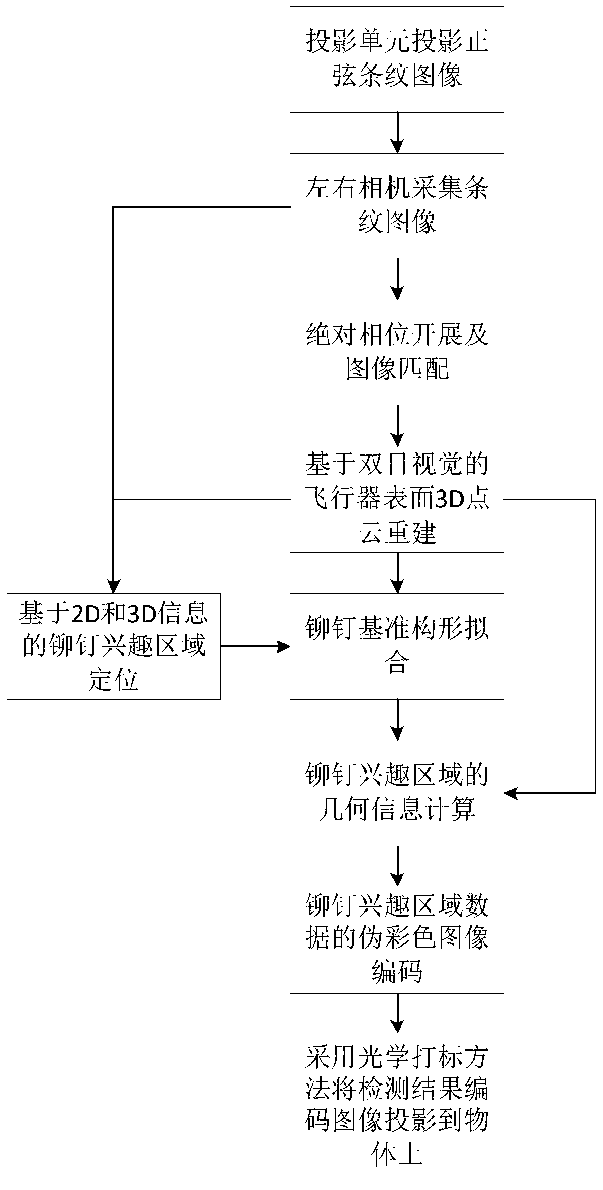
[0080] like figure 1 Shown, a kind of aircraft surface manufacturing quality inspection method based on 3D data of the present invention comprises the steps:

[0081] Use a projector to project 3 groups of 12 sinusoidal fringe images to the aircraft skin surface;

[0082] The left and right cameras collect 12 fringe images modulated by the aircraft surface;

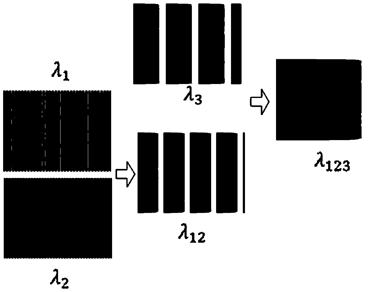
[0083] Use the image collected above to carry out phase development to obtain the absolute phase;

[0084] Match left and right camera images according to absolute phase and epipolar geometric constraints;

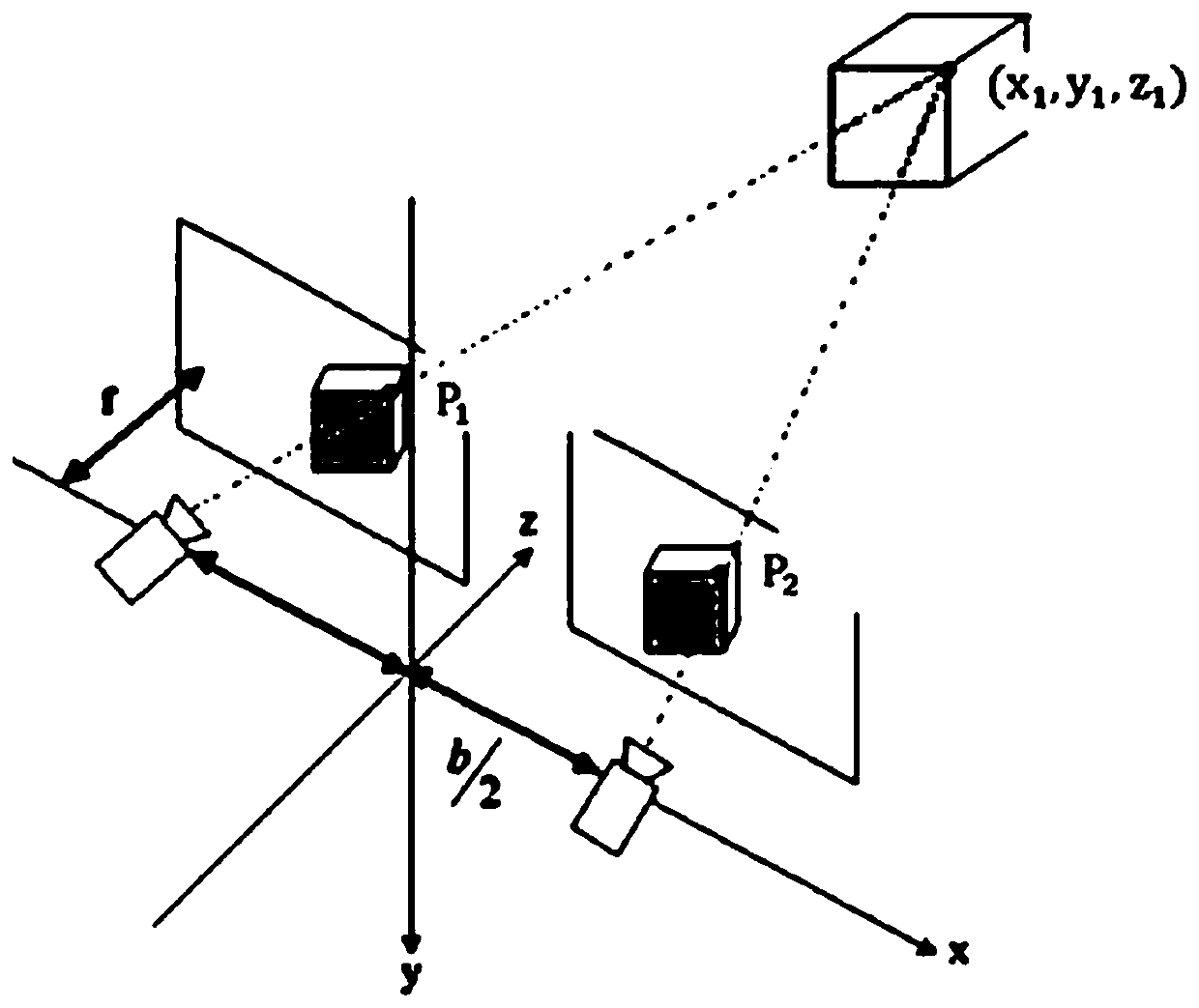
[0085] According to the image matching results and the principle of binocular vision, the 3D point cloud data model of the aircraft surface is reconstructed;

[0086] Using the two streak-free images collected by the left and right cameras, the image processing method is used to i...


PUM


Abstract

The invention relates to a 3D data based aircraft surface manufacture quality detection method. The method comprises that a series of sine stripes are projected to a surface sheath of an aircraft; left and right cameras collect stripe images modulated by the surface; the phases of the stripe images are expanded; the left and right images are matched according to phase and epipolar geometrical constraint; a 3D point cloud model of the surface of the aircraft is reconstructed; a rivet region of interest is extracted, and according to the correspondence between an image area and the 3D model, rivets are positioned in the point cloud model; a curved surface fitting method is used to obtain a reference configuration of the surface of the aircraft; the distance between a point of the rivet to the reference configuration is calculated, and a region of interest of concave-convex rivets is obtained; and a pseudo color image is coded and projected to the surface of the aircraft, and a visual result is formed. Thus, depth information of the rivet region of interest can be detected, the robustness and precision are high, a quantified and visual detection result can be provided, and a new approach suitable for the rivet region of interest of the aircraft surface is provided.

Description

technical field [0001] The invention relates to the field of automatic detection, in particular to a method for detecting the manufacturing quality of aircraft surfaces based on 3D data. Background technique [0002] The surface of the aircraft is a skin member that surrounds the outer frame of the wing, and is fixed on the frame with rivets to form the aerodynamic shape of the wing. have a major impact. Before delivery from the factory, the surface quality needs to be strictly inspected. The main inspection content includes rivet interest areas such as rivet bumps and so on. Since the aircraft is a high-value product, its design and manufacture are highly precise, and the depth error of the above-mentioned rivet region of interest is usually required to be controlled within tens of microns. [0003] At present, domestic aviation companies mainly use methods such as feeler gauges, samples, molded tires, special inspection tools, measuring tools, and manual observation to d...

Claims


Application Information

Patent Timeline
Patent Type & Authority Patents(China)
IPC IPC(8): G01B11/25
CPCG01B11/254
Inventor 夏仁波赵吉宾于彦凤陈松林陈月玲付生鹏
Owner SHENYANG INST OF AUTOMATION - CHINESE ACAD OF SCI
Why Eureka
Try Eureka