Phased array probe for automatic ultrasonic detection

A phased array probe and ultrasonic testing technology, applied in the field of phased array probes, can solve problems such as unsatisfactory, unable to meet the requirements of wear resistance and radiation resistance, and easy to be worn, so as to improve wear resistance and resistance Irradiation, improve anti-interference, reduce the effect of the number of cores

Pending Publication Date: 2018-05-11
RES INST OF NUCLEAR POWER OPERATION +1
View PDF14 Cites 2 Cited by
  • Summary
  • Abstract
  • Description
  • Claims
  • Application Information

AI Technical Summary

Problems solved by technology

[0004] At present, there are the following difficulties in applying phased array probes to remote automatic ultrasonic testing of nuclear reactor pressure vessels, steam generators, voltage stabilizers and other nuclear equipment: 1) Among the industrial phased array probe products on sale, phased array probes are not The cables and connectors are integrally designed. When the probe is damaged, the probe and the cable must be replaced together. It is impossible to quickly replace the phased array probe in a radioactive environment without replacing the cable; 2) Industrial phased array probe products on sale Among them, due to the consideration of signal transmission attenuation, the length of the probe cable is ≤20M, which cannot meet the requirement of at least 40M for the remote ultrasonic testing of nuclear reactor pressure vessels; 3) Most of the industrial phased array probe products on sale are wedges External split type, the wedge is transferred to the probe during detection
The wedge material is plexiglass, which is easy to be worn in an unprotected state, and cannot meet the requirements for wear resistance and radiation resistance of the probe for automatic ultrasonic testing of nuclear equipment

Method used


Image

  • Phased array probe for automatic ultrasonic detection
  • Phased array probe for automatic ultrasonic detection

Examples


Embodiment Construction

[0019] The present invention will be described in further detail below in conjunction with the accompanying drawings and specific embodiments.

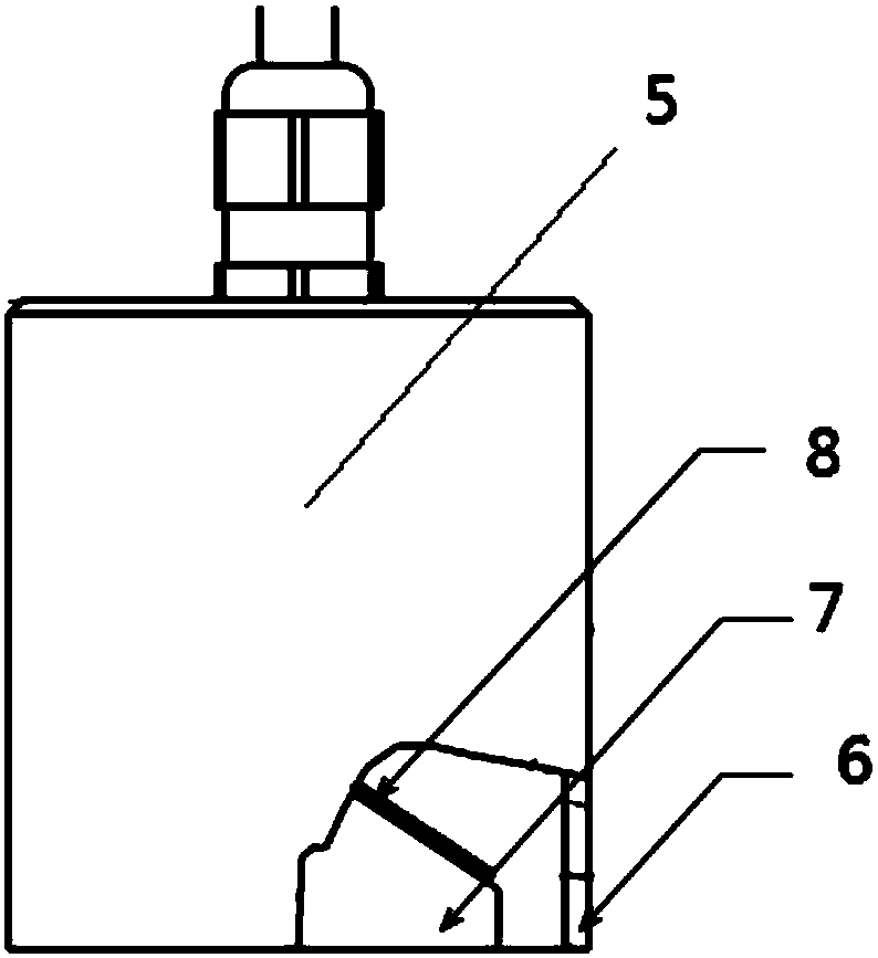
[0020] like figure 1 As shown, a phased array probe 5 for automatic ultrasonic testing includes a housing 6, a wedge 7 and a probe wafer 8, and several probe wafers 8 and wedges 7 are solidified and assembled into a housing 6 made of 0Cr18Ni9Ti stainless steel. , where 20 probe chips 8 with a width of 30mm and the wedge angle θ 1 =36.2 o The wedge 7 is fixed in the shell 6 as a whole, and the scanning surface of the wedge 7 is flush with the edge of the shell 6. The shell 6 is an integral structure, the shell wall thickness is ≥ 1mm, and the edge of the shell 6 forms an arc chamfer. .

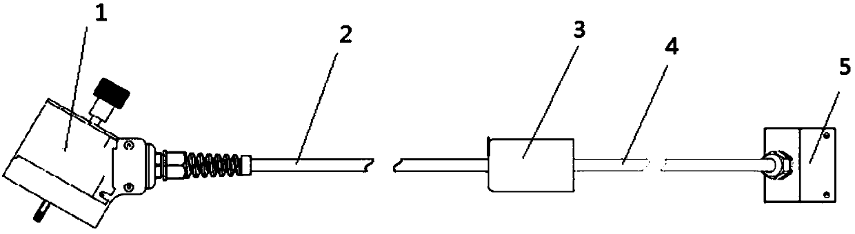
[0021] like figure 2 As shown, a phased array probe connection structure for automatic ultrasonic testing includes a tester connector 1, a cable A2, a waterproof adapter 3, a cable B4 and a phased array probe 5, wherein the detection unit connecte...


PUM

PropertyMeasurementUnit
widthaaaaaaaaaa
lengthaaaaaaaaaa
lengthaaaaaaaaaa

Abstract

The invention relates to the technical field of automatic ultrasonic detection of nuclear power plant equipment, and specifically discloses a phased array probe for automatic ultrasonic detection. Thephased array probe comprises a shell, a wedge block and probe wafers, wherein a plurality of the probe wafers and the wedge block are cured, and the cured product is integrally assembled into the stainless steel shell, such that the scanning surface of the wedge block is flush with the edge of the shell. According to the present invention, the electric cable connection of the phased array probe uses the segmented structure, such that the rapid and waterproof replacement of the phased array probe in the radioactive environment is achieved without the replacement of the electric cable; the total length of the electric cable is more than or equal to 40 m, such that the remote ultrasonic detection can be achieved; and the probe uses the wedge block built-in type integral structure, and the shell is made of the stainless steel material, such that the probe and the wedge block are protected from wear, the wear resistance and the radiation resistance of the probe are improved, and the structure integrity of the probe is ensured.

Description

technical field [0001] The invention belongs to the technical field of automatic ultrasonic detection of nuclear power plant equipment, and in particular relates to a phased array probe for automatic ultrasonic detection. Background technique [0002] The core of the nuclear power plant is the reactor pressure vessel, steam generator, voltage stabilizer and other equipment, the integrity of which is crucial to nuclear safety. With the increase of the operation time of nuclear power plants, the metal properties of metal materials and welds will gradually decrease, and metal discontinuity will also occur. Therefore, it is very necessary to conduct ultrasonic testing on these key equipment on a regular basis, so as to be able to detect dangers in welds in time. The flaws can be dealt with as soon as possible, so as to maintain and guarantee the safety of nuclear power facilities. These nuclear equipment are in a high-radiation environment, and some equipment such as reactor pr...

Claims


Application Information

Patent Timeline
Patent Type & Authority Applications(China)
IPC IPC(8): G01N29/24
CPCG01N29/24
Inventor 卢威甘文军许远欢尹鹏刘云
Owner RES INST OF NUCLEAR POWER OPERATION
Why Eureka
Try Eureka