ICP etching machine and its insulating window film heater device and temperature control method

A temperature control method and thin-film heater technology, applied in semiconductor/solid-state device manufacturing, semiconductor devices, electric solid-state devices, etc., can solve problems such as waste of labor and time costs, burden of cleaning the insulating window 150, and burning out of heating elements , to reduce the demand for maximum output power, save manpower and time costs, and increase the effect of heat conduction paths

Active Publication Date: 2020-08-07
ADVANCED MICRO FAB EQUIP INC CHINA
View PDF8 Cites 0 Cited by
  • Summary
  • Abstract
  • Description
  • Claims
  • Application Information

AI Technical Summary

Problems solved by technology

[0005] The machine performs the etching process for a long time, and process by-products produced by the etching process will be deposited on the surface of the insulating window 150. Therefore, the insulating window 150 needs to be cleaned regularly. Since the thin film heater 140 is an electrical component during cleaning, Requires additional protection from immersion, creating an additional burden on the cleaning of the insulating window 150, and additionally there is a risk of failure of the thin film heater 140 due to cleaning
[0006] Another potential problem of directly bonding the film heater 140 on the insulating window 150 is that the film heater 140, as an electrical component, has a certain service life, but the insulating window 150 will not be broken in general, so the film heater When 140 is damaged, it is necessary to remove the insulating window 150 together with the film heater 140, and then remove the film heater 140. The process is very troublesome, and the process may lead to damage and failure of the expensive insulating window 150. At the same time, disassembling the insulating window 150 is a Time-consuming and labor-intensive projects, resulting in unnecessary waste of labor and time costs
[0007] In addition, when the film heater 140 uses high power to raise the temperature, the resistance of the heating element of the film heater 140 is large, and a lot of heat is accumulated at the heating element in an instant, which is very easy to burn the glue inside the film heater 140, and even instantly The heat generated can burn out the heating element causing the thin film heater 140 to fail

Method used


Image

  • ICP etching machine and its insulating window film heater device and temperature control method
  • ICP etching machine and its insulating window film heater device and temperature control method
  • ICP etching machine and its insulating window film heater device and temperature control method

Examples


Embodiment Construction

[0037] Specific embodiments of the present invention will be further described below in conjunction with the accompanying drawings.

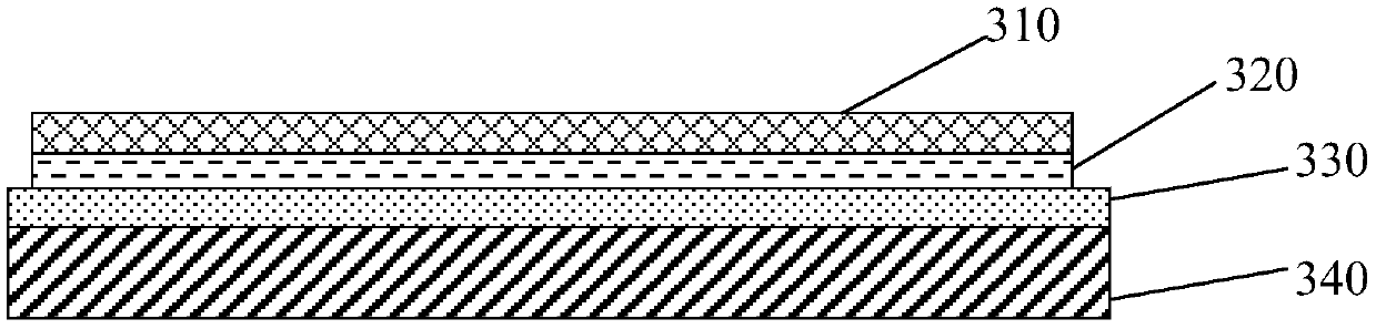
[0038] Such as image 3 As shown, it is a structural schematic diagram of Embodiment 1 of the insulating window thin film heater device, and the insulating window thin film heater device includes: an electric insulating plate 330 arranged on the top of the insulating window 340, an adhesive layer arranged on the electric insulating plate 330 320, and a thin film heater 310 disposed on the adhesive layer 320.

[0039] Both sides of the adhesive layer 320 are attached to the thin film heater 310 and the electrical insulating plate 330 respectively, so that the thin film heater 310 is fixed to the electrical insulating plate 330 through the adhesive layer 320 to form a heating module, and the heating module is fixed to the insulating plate 330 through the electrical insulating plate 330. Window 340 top.

[0040] The electrical insulating plate 33...


PUM

PropertyMeasurementUnit
thicknessaaaaaaaaaa

Abstract

The invention discloses an insulated window film heater device. The heater device comprises an electric insulation plate arranged at the top of an insulated window, an adhesive coating arranged on theelectric insulation plate and a film heater arranged on the adhesive coating; and the film heater is fixed to the electric insulation plate via the adhesive coating to form a heating module, and theheating module is fixed at the top of the insulated window via the electric insulation plate. The film heater is fixed on the electric insulation plate via the adhesive heater to form an integral body, the electric insulation plate is fixedly connected with the insulation window, the film heater is convenient to dismount and mount, the maintenance process of the film heater and the insulation window is simplified, and labor and time cost are reduced.

Description

technical field [0001] The invention relates to a heating technology in semiconductor preparation, in particular to an ICP etching machine, an insulation window film heater device and a temperature control method thereof. Background technique [0002] Such as figure 1 As shown, the upper structure of the conductance coupled plasma (Inductive Coupled Plasma, ICP) etching machine generally includes: a reaction chamber (chamber) 170, a reaction chamber top cover (chamberlid) 160 arranged on the top of the reaction chamber 170, arranged on The insulation window (insulation window) 150 on the top cover 160 of the reaction chamber, the thin film heater (kapton heater) 140 disposed on the top surface of the insulation window 150, the RF coil (RF coilkit) 130 disposed above the thin film heater 140, disposed on A housing structure 120 at the top of the reaction chamber 170, and a plurality of cooling fans 110 arranged on the top of the housing structure 120, wherein the reaction ch...

Claims


Application Information

Patent Timeline
Patent Type & Authority Patents(China)
IPC IPC(8): H01L21/67
CPCH01L21/67069H01L21/67103H01L2221/67
Inventor 左涛涛吴狄
Owner ADVANCED MICRO FAB EQUIP INC CHINA
Why Eureka
Try Eureka