Car part machining equipment

A technology for auto parts and processing equipment, applied in metal processing equipment, drilling/drilling equipment, metal processing machinery parts, etc., can solve the problems of large space required for processing, high processing cost, and achieve higher processing efficiency , The effect of using less equipment and shortening the processing time

Active Publication Date: 2018-05-15
宁波江北珂达汽车技术有限公司
View PDF11 Cites 20 Cited by
  • Summary
  • Abstract
  • Description
  • Claims
  • Application Information

AI Technical Summary

Problems solved by technology

[0005] The present invention intends to provide a kind of auto parts processing equipment to solve the problem that in the prior art, when punching the crankshaft, it is necessary to use the punching equipment and the equipment for fixing the crankshaft, resulting in too much space required for processing and high processing cost

Method used


Image

  • Car part machining equipment
  • Car part machining equipment
  • Car part machining equipment

Examples


Embodiment Construction

[0032] Further detailed explanation through specific implementation mode below:

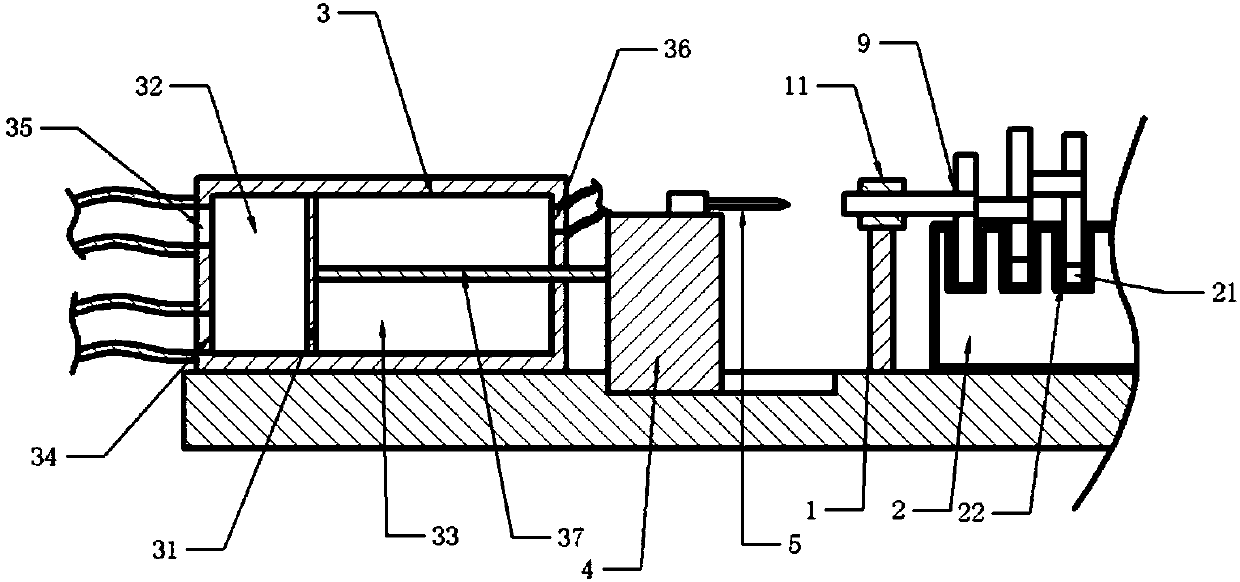
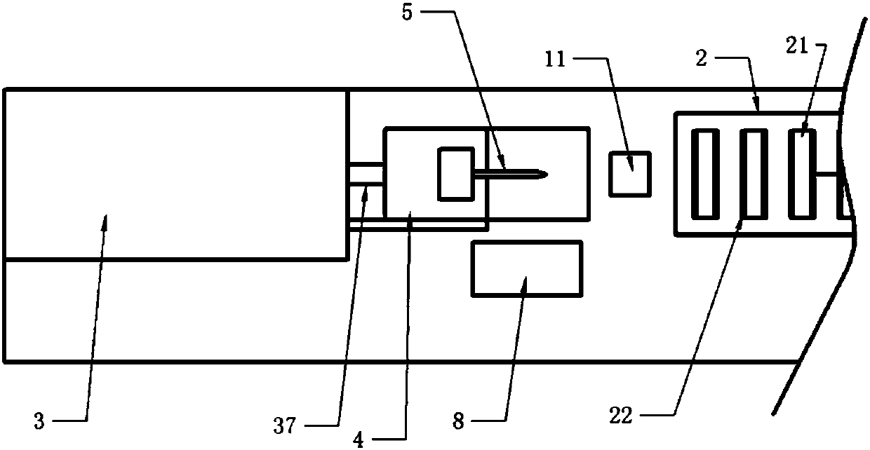
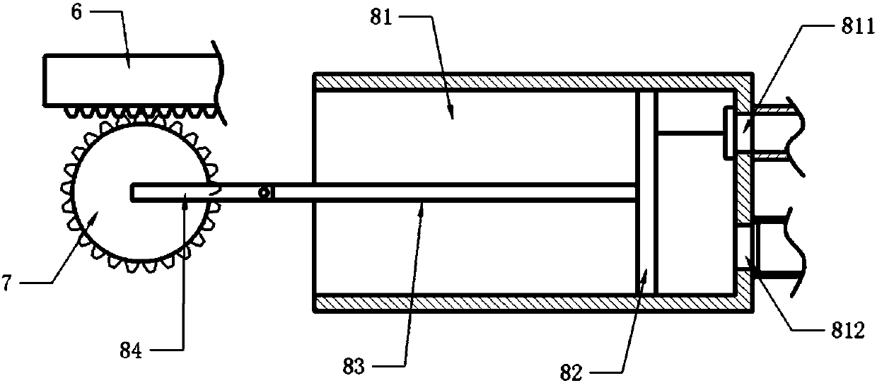
[0033] The reference signs in the accompanying drawings of the description include: support column 1, support ring 11, air bag 2, installation groove 21, gasket 22, gas storage box 3, partition 31, drive chamber 32, pressure chamber 33, first air hole 34. Exhaust port 35, second air hole 36, push rod 37, mounting table 4, drill bit 5, rack 6, gear 7, dust removal part 8, dust removal box 81, air inlet 811, air outlet 812, slide plate 82, Linkage rod 83, fixed rod 84, crankshaft 9.

[0034] The embodiment is basically as attached figure 1 Shown:

[0035]Auto parts processing equipment includes a frame, a fixing mechanism is provided in the middle of the frame, a drilling mechanism is provided at both ends of the frame, and a dust removal mechanism is installed between the fixing mechanism and the drilling mechanism. The fixing mechanism includes two supporting columns 1 and an air bag 2 arrange...


PUM


Abstract

The invention belongs to the technical field of car element machining equipment and discloses car part machining equipment comprising a rack, a fixing mechanism and a drilling mechanism. The fixing mechanism comprises two support columns and an airbag, a mounting groove is formed in the upper surface of the airbag, and a gasket is arranged on the side wall of the mounting groove. The drilling mechanism comprises a driving part and a drilling part, the driving part comprises an air storing box, and a partition plate is slidably connected to the interior of the air storing box. A pushing rod isarranged on the partition plate, the air storing box comprises a driving cavity and a press-moving cavity, and a first air hole, a second air hole and an exhaust hole are formed in the air storing box. The drilling part comprises a mounting table slidably connected to the rack, a drill bit mounted on the mounting table and a motor for driving the drill bit to rotate, and the end, away from the airstoring box, of the pushing rod is fixed to the mounting table. According to the car part machining equipment, the problems that in the prior art, when a crankshaft is punched, punching equipment andequipment for fixing the crankshaft are needed for use, thus the space needed by machining is large, and the machining cost is high are solved.

Description

technical field [0001] The invention belongs to the field of processing equipment for automobile components, and in particular relates to processing equipment for automobile parts. Background technique [0002] The crankshaft is a commonly used auto part and the most important part of the engine. It is mainly used to bear the force transmitted by the connecting rod, convert it into torque output, and drive other accessories on the engine to work. When the crankshaft is in use, it is subjected to the joint action of the rotating centrifugal force, the periodically changing gas inertial force and the reciprocating inertial force, so that the crankshaft bears the bending torsional load. Therefore, the crankshaft needs better lubrication when in use, usually by drilling holes on the end face of the shaft to achieve lubrication. [0003] In order to realize the punching of the crankshaft, the Chinese patent with the patent publication number CN205200600U provides a kind of crank...

Claims


Application Information

Patent Timeline
Patent Type & Authority Applications(China)
IPC IPC(8): B23Q3/08B23B39/16B23Q1/30B23Q11/10B23Q11/00
CPCB23B39/16B23Q1/30B23Q3/062B23Q3/08B23Q11/005B23Q11/10B23Q2703/105
Inventor 孙文清
Owner 宁波江北珂达汽车技术有限公司
Why Eureka
Try Eureka