Unlock instant, AI-driven research and patent intelligence for your innovation.
Hydraulic loop of pump-controlled single rod piston cylinder
What is Al technical title?
Al technical title is built by PatSnap Al team. It summarizes the technical point description of the patent document.
A hydraulic circuit, single-rod technology, used in fluid pressure actuating devices, servo motors, servo motor components, etc., can solve the problems of sudden changes in cylinder speed, high cost, and unsatisfactory energy-saving effects under alternating loads. Rapid speed change, low cost, good anti-alternating load characteristics
Inactive Publication Date: 2018-05-15
TAIYUAN UNIVERSITY OF SCIENCE AND TECHNOLOGY
View PDF7 Cites 0 Cited by
Summary
Abstract
Description
Claims
Application Information
AI Technical Summary
This helps you quickly interpret patents by identifying the three key elements:
Problems solved by technology
Method used
Benefits of technology
Problems solved by technology
[0004] At present, two high-pressure hydraulic pumps are used in the pump-controlled single-rod piston-cylinder circuit, or a hydraulic transformer is installed in the high-voltage circuit, or two hydraulic control check valves are used to compensate for asymmetric flow, which has high cost and poor energy-saving effect. Problems such as sudden changes in cylinder speed under ideal and alternating loads
Method used
Image
Click on the blue label to locate the original text in one second.
Reading with bidirectional positioning of images and text.
Examples
Embodiment 1
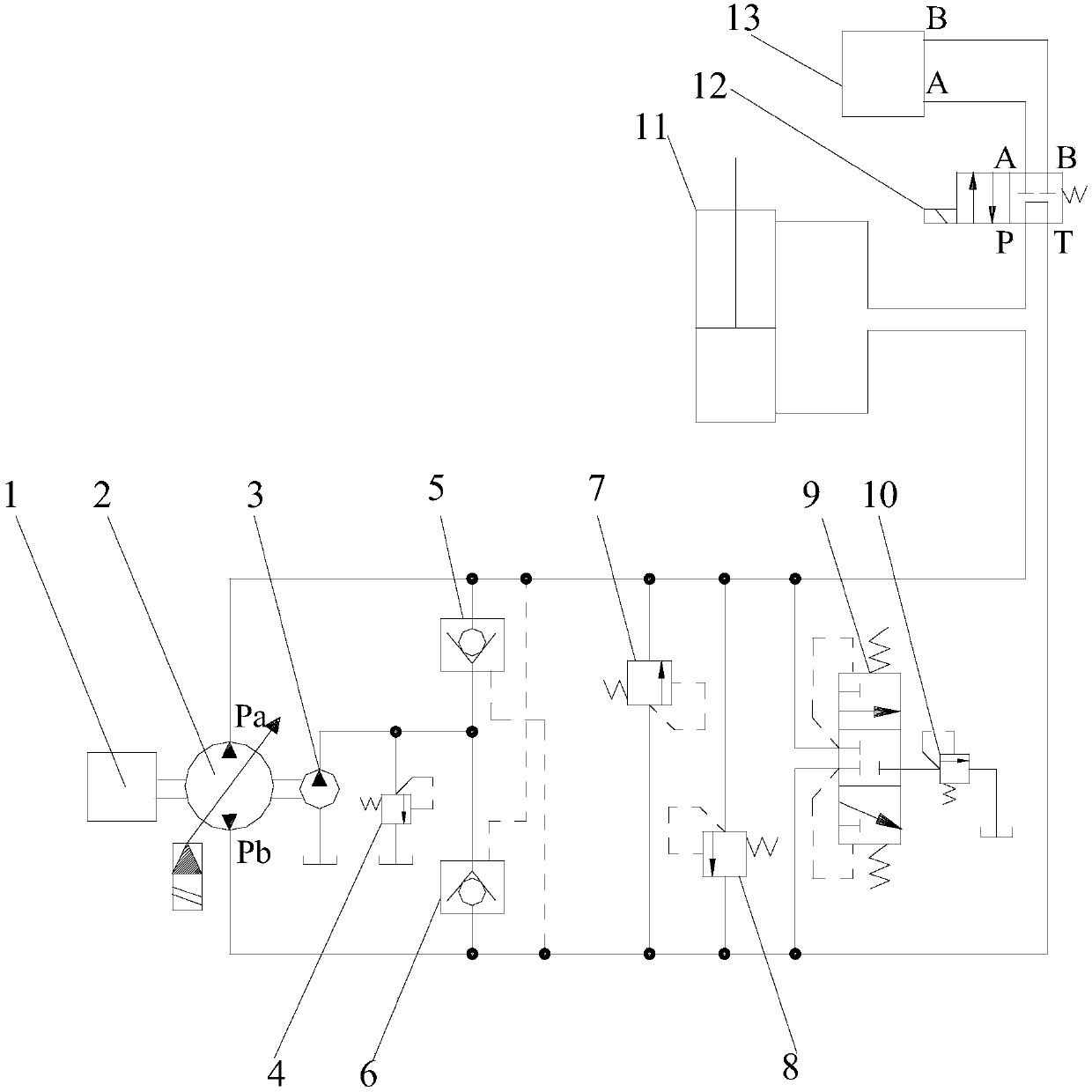
[0019] Such as figure 2 As shown, it includes prime mover 1, main pump 2, charge pump 3, first and second low-pressure relief valves 4 and 10, first and second hydraulic control check valves 5 and 6, first and second safety valves Valves 7, 8, shuttle valve 9, working cylinder 11, high pressure reversing valve 12, hydraulic transformer 13, oil tank, controller;
[0020] Prime mover 1, main pump 2, charge pump 3, first and second low pressure relief valves 4 and 10, first and second hydraulic control check valves 5 and 6, first and second safety valves 7 and 8, Shuttle valve 9, working cylinder 11, high-pressure reversing valve 12, hydraulic transformer 13, oil tank, and controller are connected in such a way that the main shafts of prime mover 1, main pump 2 and charge oil pump 3 are connected, and the Pa port of main pump 2 is connected to the The oil outlet of the first hydraulically controlled check valve 5, the hydraulically controlled port of the second hydraulically co...
Embodiment 2
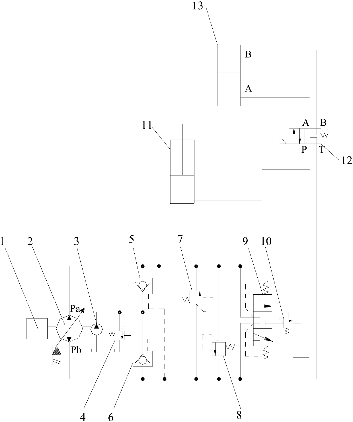
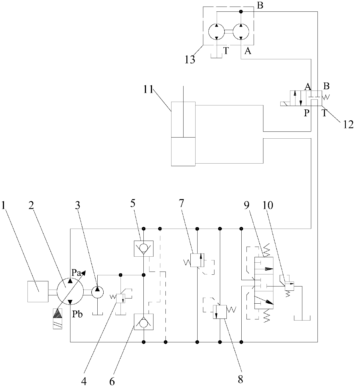
[0029] Such as image 3 As shown, it includes prime mover 1, main pump 2, charge pump 3, first and second low-pressure relief valves 4 and 10, first and second hydraulic control check valves 5 and 6, first and second safety valves Valves 7, 8, shuttle valve 9, working cylinder 11, high pressure reversing valve 12, hydraulic transformer 13, oil tank, controller;
[0030] Prime mover 1, main pump 2, charge pump 3, first and second low pressure relief valves 4 and 10, first and second hydraulic control check valves 5 and 6, first and second safety valves 7 and 8, Shuttle valve 9, working cylinder 11, high-pressure reversing valve 12, hydraulic transformer 13, oil tank, and controller are connected in such a way that the main shafts of prime mover 1, main pump 2 and charge oil pump 3 are connected, and the Pa port of main pump 2 is connected to the The oil outlet of the first hydraulically controlled check valve 5, the hydraulically controlled port of the second hydraulically con...
PUM
Abstract
The invention discloses a hydraulic loop of a pump-controlled single rod piston cylinder and belongs to the technical field of hydraulic transmission. The hydraulic loop comprises a prime motor, a main pump, an oil supplementing pump, a first hydraulic control one-way valve, a second hydraulic control one-way valve, a shuttle valve, a working cylinder, a hydraulic transformer, a high-pressure reversing valve, an oil tank and a controller. The hydraulic loop is characterized in that the high-pressure reversing valve is a two-position four-way electromagnetic reversing valve, and a right workingposition of the reserving valve has the function of an M-shaped sliding valve; a first working cavity and a second working cavity of the working cylinder communicate with a port Pa of the main pump and a port P of the reserving valve correspondingly; a port T of the reserving valve communicates with a port Pb of the main pump; and a port A and a port B of the reserving valve communicate with a port A and a port B of the hydraulic transformer correspondingly. The hydraulic loop has the advantages that when the working cylinder is in the stable heavy-load and load working conditions, the two hydraulic control one-way valves are adopted to compensate the asymmetrical flow, so that the energy efficiency is high; and when the working cylinder is in the alternating load working condition, the hydraulic transformer is adopted to compensate the asymmetrical flow, so that sudden change of the speed of the working cylinder is avoided.
Description
technical field [0001] The invention belongs to the technical field of hydraulic transmission, and in particular relates to a hydraulic circuit of a pump-controlled single-rod piston cylinder. Background technique [0002] The pump control system is a hydraulic system that directly controls the working speed of the execution unit (hydraulic motor or hydraulic cylinder) through the variable pump, cancels the multi-way valve, avoids throttling loss, and has high energy efficiency. The pump control cylinder circuit is divided into a pump control symmetrical cylinder and a pump control single rod piston cylinder. The research on pump-controlled symmetrical cylinder technology started earlier and has been perfected day by day. However, the pump-controlled single-rod piston cylinder technology is still immature, mainly because the working area of the piston chamber and the piston rod chamber of the single-rod piston cylinder is different, and the flow rate of the double chamber...
Claims
Application Information
Patent Timeline
Application Date:The date an application was filed.
Publication Date:The date a patent or application was officially published.
First Publication Date:The earliest publication date of a patent with the same application number.
Issue Date:Publication date of the patent grant document.
PCT Entry Date:The Entry date of PCT National Phase.
Estimated Expiry Date:The statutory expiry date of a patent right according to the Patent Law, and it is the longest term of protection that the patent right can achieve without the termination of the patent right due to other reasons(Term extension factor has been taken into account ).
Invalid Date:Actual expiry date is based on effective date or publication date of legal transaction data of invalid patent.
IPC IPC(8): F15B11/17F15B13/02
CPCF15B11/17F15B13/02F15B13/027
Inventor 仉志强宋建丽贾跃虎李永堂刘志奇樊万锁
Owner TAIYUAN UNIVERSITY OF SCIENCE AND TECHNOLOGY

