A low leakage connector

A connector and low-leakage technology, which is applied in the field of integrated circuit testing, can solve the problems of low-leakage test module connection, testing, and test efficiency drop.

Active Publication Date: 2020-07-21
INST OF MICROELECTRONICS CHINESE ACAD OF SCI
View PDF5 Cites 0 Cited by
  • Summary
  • Abstract
  • Description
  • Claims
  • Application Information

AI Technical Summary

Problems solved by technology

[0004] Aiming at the problems existing in the prior art, the embodiment of the present invention provides a low-leakage connector, which is used to solve the problem that the low-leakage connector in the prior art cannot connect and test the low-leakage test module with multiple PIN pins, causing the test Technical problems with reduced efficiency

Method used


Image

  • A low leakage connector

Examples


Embodiment 1

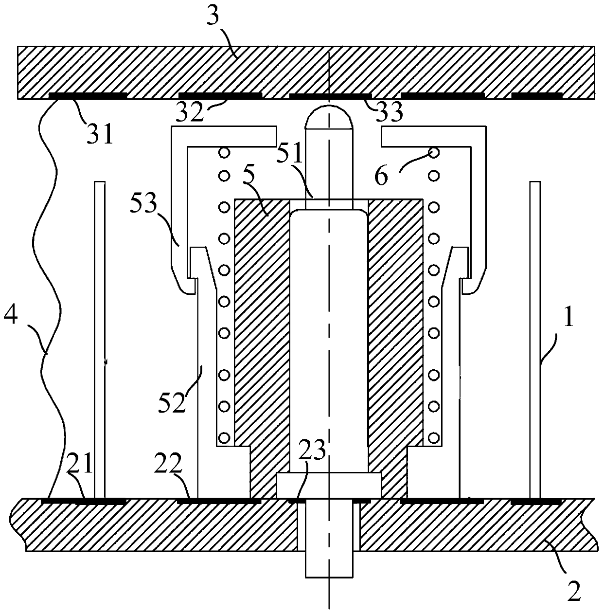
[0034] This embodiment provides a low leakage connector, such as figure 1 As shown, the low leakage connector includes: a plurality of retractable connection mechanisms, at least ground shielding mechanism 1; wherein,

[0035] One end of a plurality of said stretchable connection mechanisms is respectively connected to the first signal electrode 23 and the first equipotential electrode 22 of the first test substrate 2; the other end of said stretchable connection mechanism is respectively connected to the second test The second signal electrode 33 of the substrate 3 is connected to the second equipotential electrode 32; the ground shielding mechanism 1 is installed on the ground electrode 21 of the first test substrate 2 or on the ground electrode 31 of the second test substrate 3, for A plurality of said retractable mechanisms perform ground shielding. The ground shielding mechanism 1 is used to shield the retractable connection mechanism and eliminate the influence of exter...

Embodiment 2

[0056] In practical applications, the number of low-leakage connectors can be determined according to the number of PIN pins to be tested on the test substrate. The low-leakage connector provided in Embodiment 1 performs a connection test on each PIN pin, and the specific implementation is as follows:

[0057] The low-leakage connector includes 6 (because the first test substrate 2 and the second test substrate 3 are divided into 6 test cavities), the ground shielding mechanism 1; wherein,

[0058] see figure 1 , one end of the telescopic connection mechanism is connected to the first signal electrode 23 and the first equipotential electrode 22 of the first test substrate 2 respectively; the other end of the telescopic connection mechanism is respectively connected to the second test substrate The second signal electrode 33 of 3 is connected to the second equipotential electrode 32; the ground shielding mechanism 1 is installed on the ground electrode 21 of the first test sub...


PUM


Abstract

The embodiment of the invention provides a low-electric leakage connector. The low-electric leakage connector comprises multiple telescopic connection mechanisms; one end of each telescopic connectionmechanism is correspondingly connected with a first signal electrode of a first test substrate and a first equipotential electrode respectively, and the other end of the telescopic connection mechanism is correspondingly connected with a second signal electrode of a second test substrate and a second equipotential electrode respectively; a ground shield mechanism is arranged on the ground electrode of the first test substrate or the ground electrode of the second test substrate; and a ground connection part is connected between the ground electrode of the first test substrate and the ground electrode of the second test substrate. Thus, according to the low-electric leakage connector, pins of the first test substrate and the second test substrate can be electrically connected while the low-electric leakage performance is kept, the number of low-electric leakage connectors can be determined according to the number of to-be-connected pins, the multiple low-electric leakage connectors canfurther be used to connect and test a low-electric leakage test substrate with multiple pins, and the test efficiency is improved.

Description

technical field [0001] The invention belongs to the technical field of integrated circuit testing, in particular to a low-leakage connector. Background technique [0002] The connector is an important part to connect two test modules, and the low-leakage connector is mainly used in the high-precision measurement system of semiconductor devices. [0003] Low leakage test is a difficult point in the test. The main problem is that environmental interference and parasitic capacitance will affect the measurement signal. A common practice is to develop a triaxial test cable. The core wire provides the measurement signal, the equipotential line GUARD provides equipotentiality to eliminate the influence of parasitic capacitance, and the outer skin of the ground wire shields external interference signals. Using this cable, you can get less than 50fA ( femtoampere) measurement capabilities, and are widely used in low leakage test systems. However, this cable structure is difficult t...

Claims


Application Information

Patent Timeline
Patent Type & Authority Patents(China)
IPC IPC(8): G01R1/04G01R31/28
CPCG01R1/0416G01R31/2808G01R31/2818
Inventor 曾传滨王瑞恒倪涛高林春李晓静罗家俊
Owner INST OF MICROELECTRONICS CHINESE ACAD OF SCI
Why Eureka
Try Eureka