A method for calibrating a coherence factor of an excimer lithographic lighting system

A kind of technology of excimer laser and illumination system

Inactive Publication Date: 2018-05-15
SICHUAN UNIV
View PDF6 Cites 0 Cited by
  • Summary
  • Abstract
  • Description
  • Claims
  • Application Information

AI Technical Summary

Problems solved by technology

In this device, the photosensitive surface of the CCD must be on the same plane as the focal plane of the lens. Under the current technical background, there is no unified method to realize that the photosensitive surface of the CCD and the focal plane of the lens are on the same plane. The device has its own independent method to make the CCD photosensitive surface as close as possible to the focal plane of the lens.

Method used


Image

  • A method for calibrating a coherence factor of an excimer lithographic lighting system
  • A method for calibrating a coherence factor of an excimer lithographic lighting system
  • A method for calibrating a coherence factor of an excimer lithographic lighting system

Examples


Embodiment Construction

[0019] The present invention will be further described in detail below in conjunction with the accompanying drawings, working principles and implementation methods.

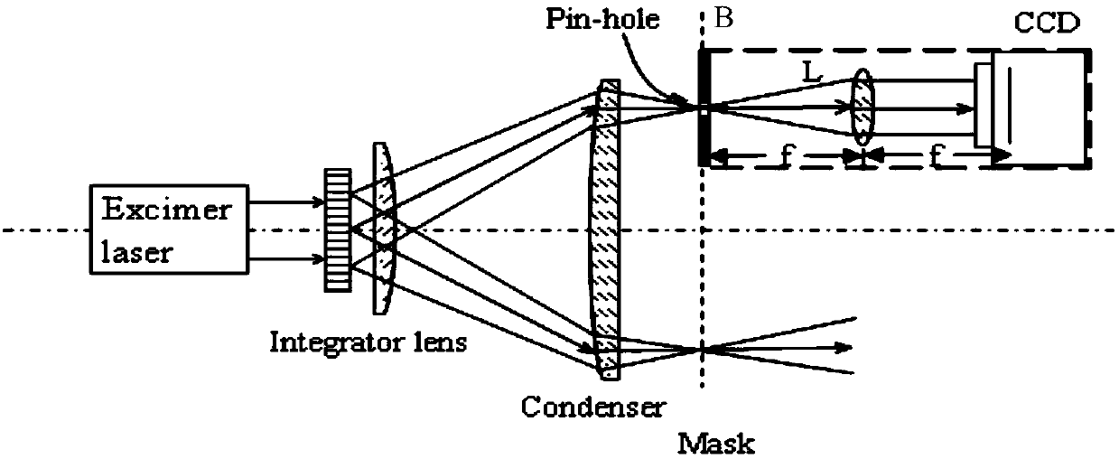
[0020] exist Figure 4 In , after the pinhole and the lens group are fixed, a coordinate system is established on the lens , is the direction of the optical axis of the lens. Establish a coordinate system on the photosensitive surface of the CCD , Located in the photosensitive surface of CCD, is its normal direction, such as Figure 5 As shown, the corresponding unit vector . When the CCD photosensitive surface around shaft rotation angle, rotate around the Ym axis angle, coordinate system and The transformation matrix between is:

[0021] (1)

[0022] After rotation, the normal direction of the CCD photosensitive surface relative to the lens coordinates is,

[0023] (2)

[0024] for Figure 6 , there is a certain angle between the CCD photosensitive surface and the focal plane o...


PUM


Abstract

The invention relates to a coherence factor measuring device based on CCD imaging for a lithographic system. Calibration of consistency between a CCD light-sensitive surface and a lens focal plane isachieved through a pin hole, a rotating platform, and a manually operated X-Y displacement platform. A proper coordinate system is built on a CCD, a point on the pin hole is selected and is imaged onthe CCD through a lens, and the centroid of the image point is calculated to obtain a first coordinate point A'. The rotating platform is rotated by 90 degrees to obtain a second image, and the centroid of the second image is calculated to obtain a second coordinate point B'. The rotating platform is rotated by the same manner to obtain a third coordinate point A'' and a fourth coordinate point B'' respectively. The four coordinate points are utilized to establish a correlation. When a difference between a distance from the A' to the A'' and a distance from the B' to the B'' is large, it is determined that a certain included angle is between the CCD and the lens focal plane, the included angle is calculated through the correlation established through the four coordinate points, and then the angle of the CCD light-sensitive surface is adjusted until the difference between the distance from the A' to the A'' and the distance from the B' to the B'' is arbitrarily small, thus achieving substantial consistency between the CCD light-sensitive surface and the lens focal plane.

Description

technical field [0001] The invention relates to a coherence factor measuring device for an excimer laser lithography illumination system. The method well realizes the calibration of a certain included angle between a CCD photosensitive surface and a lens focal plane in the measuring device. Background technique [0002] In the manufacture of integrated circuits, the process technology of using the principle of optical-chemical reaction and chemical and physical etching methods to transfer the mask pattern to the surface of the single crystal to form effective functional patterns is called photolithography. Optical exposure lithography has achieved great development due to its advantages of low cost, high resolution, simple equipment, and convenient operation. Optical exposure lithography includes contact, proximity lithography, laser interference and optical projection lithography, among which excimer laser lithography is a kind of optical projection lithography. [0003] A...

Claims


Application Information

Patent Timeline
IPC IPC(8): G03F7/20
CPCG03F7/70025G03F7/7055G03F7/7085
Inventor 曹益平
Owner SICHUAN UNIV
Why Eureka
Try Eureka