
Cooling and heat radiation structure of capacitor

A heat dissipation structure and capacitor technology, applied in capacitors, electrical components, etc., can solve problems such as temperature rise and damage to the capacitor shell, and achieve a good effect of cooling and heat dissipation

Active Publication Date: 2018-05-15
宁波博恩电气有限公司
View PDF5 Cites 6 Cited by
  • Summary
  • Abstract
  • Description
  • Claims
  • Application Information

AI Technical Summary

Problems solved by technology

This invention uses a heat conduction cylinder to absorb the heat of the capacitor element, and then transfers the heat to the shell of the capacitor through the heat conduction beam and the arc-shaped heat conduction sheet to improve the heat dissipation performance of the capacitor. This invention only absorbs the heat generated by the capacitor, Then transfer, but finally the shell temperature of the capacitor also rises, which may damage the shell of the capacitor. At the same time, there is an arc-shaped heat conduction sheet to absorb the heat of the shell and transfer it to the capacitor element.

Method used


Image

  • Cooling and heat radiation structure of capacitor

Examples


Embodiment Construction

[0016] Further detailed explanation through specific implementation mode below:

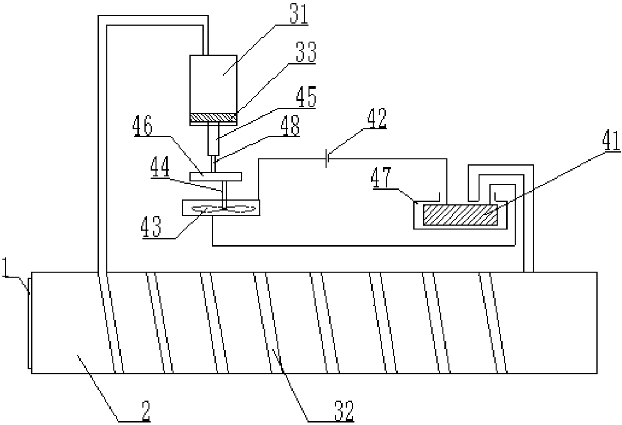
[0017] The reference signs in the drawings of the description include: capacitor 1, insulating paper 2, water tank 31, water pipe 32, piston 33, cardboard 41, power supply 42, fan 43, rotating shaft 44, bushing 45, deceleration gear set 46, cardboard slot 47, threaded rod 48.

[0018] Such as figure 1 Shown is a cooling and heat dissipation structure for a capacitor, including a cooling mechanism, a heat dissipation mechanism, and a plurality of capacitor elements connected in parallel. The capacitor element is wrapped with a layer of insulating paper 2 .

[0019] Wherein, the cooling mechanism includes a water tank 31 and a water pipe 32, the water pipe 32 is connected to the water tank 31, and the water pipe 32 is spirally wound on the capacitor 1 wrapped by the insulating paper 2, so that the capacitor 1 part can receive a uniform cooling effect, and at the same time A part of the gap is res...


PUM


Abstract

The invention relates to the technical field of power system capacitors and particularly relates to a cooling and heat radiation structure of a capacitor, which comprises a cooling mechanism, a heat radiation mechanism and multiple parallel capacitor elements, wherein the capacitor element is coated with a layer of insulating paper; the cooling mechanism comprises a water tank and a water pipe; one side of the water tank is communicated with the water pipe, and the other side of the water tank is provided with a sliding piston; the water pipe is wound on the capacitor element coated by the insulating paper; the heat radiation mechanism comprises a power supply, a fan, a paper plate and a paper plate groove; the paper plate, the fan and the power supply are connected by wires; the fan is fixedly connected with a rotating shaft; the rotating shaft is connected with a speed reduction gear set through an input shaft; the output shaft of the speed reduction gear set is connected with a threaded rod; the threaded rod is connected with a casing; and the casing is fixedly connected onto the piston. The capacitor is cooled by using the water pipe to be wound on the capacitor and water to flow in the water pipe, the fan is also rotated, and the cooling and heat radiation effects of the capacitor are further enhanced.

Description

technical field [0001] The invention relates to the technical field of electric power system capacitors, in particular to a cooling and cooling structure for capacitors. Background technique [0002] With the rapid development of the modern IT industry, power system automation has become the focus of people's attention, and the power sector has also made corresponding regulations on energy conservation. The power factor of general enterprises is usually between 0.65 and 0.8. If the enterprise wants to achieve Compensation must be made for power equipment to meet the country's electricity requirements. As a basic component of the circuit, the capacitor plays an important role in the circuit. Its quality directly affects the working state of the circuit. As a high-power component, the capacitor is easy to generate heat during long-term use. , it is easy to cause self-explosion, which will cause other electronic components around the capacitor to be damaged by it, thereby losi...

Claims


Application Information

Patent Timeline
IPC IPC(8): H01G2/08
CPCH01G2/08
Inventor 陈亮
Owner 宁波博恩电气有限公司
Learn More