Oxygen dissolving tank and breeding water body oxygenation system

A tank and dissolved oxygen technology, applied in the field of aquaculture water aeration system, can solve the problems of waste of pure oxygen resources, inability to use soil ponds, and high cost of aquaculture, and achieve the effects of low power consumption, simple structure, and convenient use

Pending Publication Date: 2018-05-18
汤润胜
View PDF5 Cites 1 Cited by
  • Summary
  • Abstract
  • Description
  • Claims
  • Application Information

AI Technical Summary

Problems solved by technology

But the disadvantage is that a large amount of pure oxygen cannot be dissolved into the water body, resulting in a waste of pure oxygen resources, and the investment in equipment is large, the area is large, and the cost of breeding is high, so it cannot be used in conventional earthen ponds.

Method used


Image

  • Oxygen dissolving tank and breeding water body oxygenation system
  • Oxygen dissolving tank and breeding water body oxygenation system
  • Oxygen dissolving tank and breeding water body oxygenation system

Examples


Embodiment 1

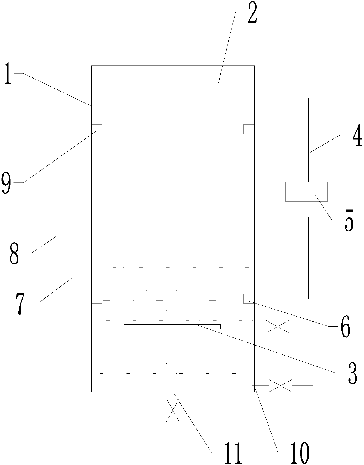
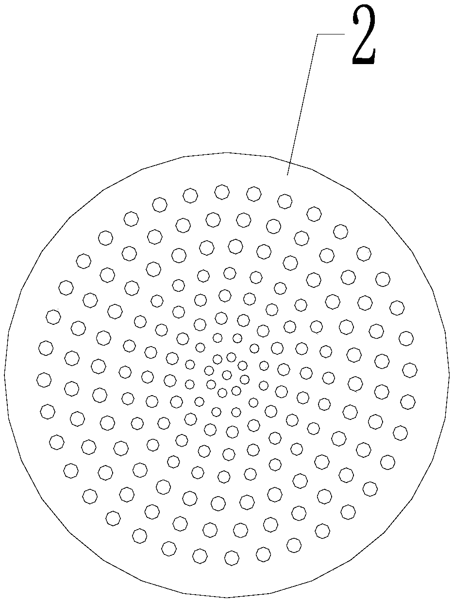
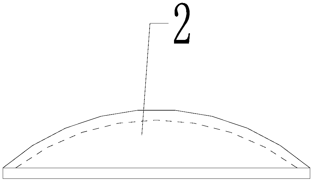
[0032] Such as figure 1 , figure 2 and image 3As shown, the present embodiment includes a closed tank body 1, on which the first water inlet located at the top of the tank body 1, the first air inlet located at the lower part of the side wall of the tank body 1 and the tank body located at 1 the water outlet 10 at the lower part of the side wall. A main water body cutter is installed in the upper part of the tank body 1, and the main water body cutter includes a second water inlet and a plurality of water outlet holes, and the second water inlet communicates with the first water inlet through a connecting pipe; or the The second water inlet is formed by the first water inlet. In this embodiment, preferably, the main water body cutter includes a circular water outlet plate 2 and an upper cover (not shown in the drawings) covering the water outlet plate 2 , and the second water inlet is located on the upper cover. The water outlet holes are located on the water outlet plat...

Embodiment 2

[0038] Such as figure 1 , figure 2 , image 3 , Figure 4 , Figure 5 , Figure 6 and Figure 7 As shown, this embodiment includes the dissolved oxygen tank described in Embodiment 1, and also includes a suction pipe 12 , a water inlet pipe 14 , a water outlet pipe 16 , a water return pipe 17 , a branch pipe 15 and an oxygen source 18 . One end of the water suction pipe 12 is tee-connected with one end of the water inlet pipe 14 and one end of the branch pipe 15 , and a water pump 13 is installed on the water suction pipe 12 . The other end of the water inlet pipe 14 communicates with the first water inlet of the tank body 1 , and the other end of the branch pipe 15 is connected with one end of the water outlet pipe 16 and one end of the return pipe 17 in a three-way connection. The other end of the water outlet pipe 16 communicates with the water outlet 10 of the tank body 1 . Described oxygen source 18 is communicated with the air inlet of tank body 1 through pipelin...


PUM


Abstract

The invention discloses an oxygen dissolving tank and a breeding water body oxygenation system. A first water inlet, a first air inlet and a water outlet in the lower portion of a tank body are formedin the closed tank body; a main water body cutter and a main aeration device are arranged in the tank body, a hole is formed in the upper portion of the tank body to be connected with a circulating air pipe and provided with an air pump, and the other end of the circulating air pipe extends into the tank body and is connected with an auxiliary aeration device on the lower portion in the tank body, so that the oxygen dissolving tank capable of effectively avoiding pure oxygen waste and remarkably increasing the dissolved oxygen amount is provided. The oxygen dissolving tank is used for designing the novel breeding water body oxygenation system, the utilization rate of pure oxygen and the dissolved oxygen degree of a water body are remarkably increased, and the breeding water body oxygenation system has the advantages of being ingenious in concept, simple in structure, small in occupied area, convenient to use, low in power consumption, low in air consumption and the like.

Description

technical field [0001] The invention belongs to the technical field of water body oxygenation, and in particular relates to a dissolved oxygen tank and an aquaculture water oxygenation system designed using the oxygen dissolved tank. Background technique [0002] At present, some water bodies need to increase the dissolved oxygen, especially the aquaculture water, and the dissolved oxygen has a significant impact on the output value. Studies have shown that the higher the dissolved oxygen in the water, the greater the breeding density, the shorter the production cycle, and the greater the output value per unit time and unit of water; when the dissolved oxygen in the water exceeds 250% of the saturated dissolved oxygen in the water, %, some aquatic organisms will suffer from oxygen poisoning and gas bubble disease, and the production value will drop accordingly, and when it is serious, there will be a large number of deaths. With the improvement of living standards, the supp...

Claims


Application Information

Patent Timeline
IPC IPC(8): A01K63/04
CPCA01K63/042
Inventor 汤润胜
Owner 汤润胜
Why Eureka
Try Eureka