A graded condensation device for biomass pyrolysis liquefaction polygeneration

A biomass pyrolysis and staged condensation technology, applied in multiple-effect/separative condensation, separation methods, steam condensation, etc., can solve the problems of poor heat exchange effect, large heat exchange coefficient, difficult temperature fine-tuning, etc., to improve heat exchange High efficiency, high heat exchange efficiency and good condensation effect

Active Publication Date: 2019-07-19
HUAZHONG UNIV OF SCI & TECH
View PDF4 Cites 0 Cited by
  • Summary
  • Abstract
  • Description
  • Claims
  • Application Information

AI Technical Summary

Problems solved by technology

[0003] These existing condensation methods have the following problems: First, the heat exchange effect of the heat exchanger in the prior art is poor, and the pyrolysis volatiles flow in a laminar flow in the through pipe, the heat transfer coefficient is small, and the condensation effect is poor; on the other hand , the heat transfer coefficient of air as the cooling medium is too small, the condensation effect is poor, and the bio-oil acquisition rate is low; while the heat transfer coefficient of water as the cooling medium is too large, it is difficult to fine-tune the temperature, and it is difficult to flexibly realize hierarchical regulation; in addition, the cooling medium Usually there is only one inlet. When the temperature of a certain heat exchange area is changed by adjusting the cooling medium flow rate, other heat exchange areas will also change accordingly, and it is impossible to ensure that each area is in the optimal temperature range.

Method used


Image

  • A graded condensation device for biomass pyrolysis liquefaction polygeneration
  • A graded condensation device for biomass pyrolysis liquefaction polygeneration
  • A graded condensation device for biomass pyrolysis liquefaction polygeneration

Examples


Embodiment Construction

[0024] In order to make the objectives, technical solutions, and advantages of the present invention clearer, the following further describes the present invention in detail with reference to the accompanying drawings and embodiments. It should be understood that the specific embodiments described herein are only used to explain the present invention, but not to limit the present invention. In addition, the technical features involved in the various embodiments of the present invention described below can be combined with each other as long as they do not conflict with each other.

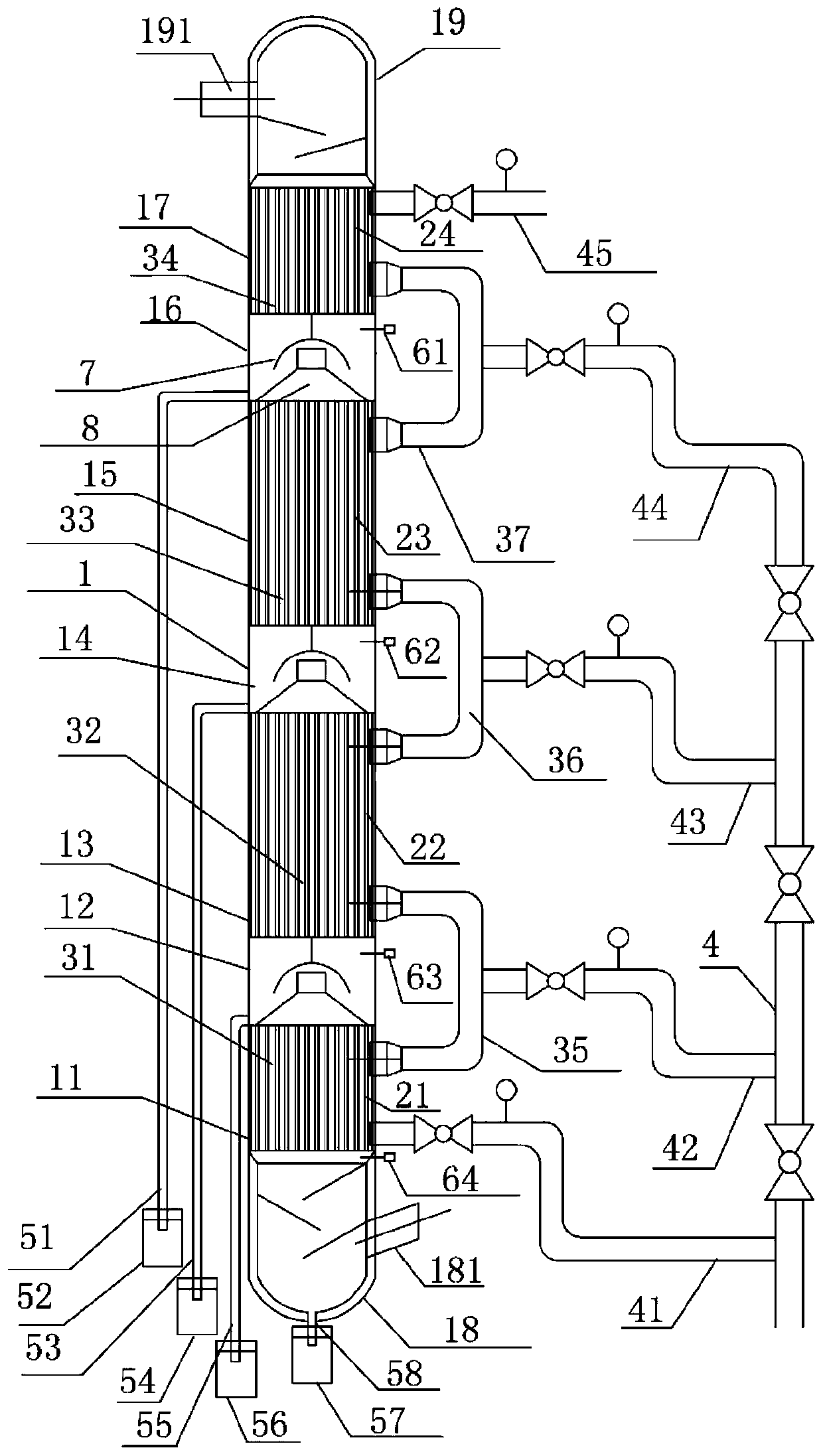
[0025] Such as figure 1 As shown, an embodiment of the present invention provides a hierarchical condensation device for biomass pyrolysis, liquefaction and poly-generation, including a main cylinder 1 and multi-stage heat exchanges arranged inside the main cylinder at intervals along the height direction of the main cylinder Condensing unit, wherein the bottom of the main cylinder 1 is connected to t...


PUM


Abstract

The invention belongs to the field of condensation devices, and particularly discloses a fractional condensation device for biomass pyrolysis liquefaction polygeneration. The device comprises a main cylinder body and multiple stages of heat exchange condensation units, the bottom of the main cylinder body is connected with a lower sealing head provided with a pyrolysis volatile inlet, and the topof the main cylinder body is connected with an upper sealing head provided with a pyrolysis gas outlet; an oil collecting unit is arranged between every two stages of the heat exchange condensation units and includes a heat exchange cylinder body and a pyrolysis volatile pipeline disposed in the heat exchange cylinder body, a heat transfer oil cooling cavity is formed between the inner wall of each heat exchange cylinder body and the outer wall of the corresponding pyrolysis volatile pipeline, the heat transfer oil cooling cavities of the adjacent heat exchange condensation units are connectedby bending pipes, and the bending pipes are connected with a heat transfer oil conveying pipe; the heat transfer oil cooling cavities located in the lowermost and uppermost heat exchange condensationunits are provided with a heat transfer oil inlet pipe and a medium temperature heat transfer oil outlet pipe, wherein the heat transfer oil inlet pipe and the medium temperature heat transfer oil outlet pipe are connected with the heat transfer oil conveying pipe. The device can achieve the fractional cyclic condensation of biomass pyrolysis volatiles, and has the advantages of a good condensation effect, high heat exchange efficiency, a high bio-oil acquisition rate and the like.

Description

Technical field [0001] The invention belongs to the field of condensing devices, and more specifically, relates to a staged condensing device for biomass pyrolysis liquefaction polygeneration. Background technique [0002] At present, in the process of staged condensation of biomass pyrolysis volatiles to collect bio-oil, the condensation system usually adopts multiple sets of heat exchangers composed of pipes in series, and the cooling medium is usually air or water. [0003] These existing condensation methods have the following problems: First, the heat exchange effect of the prior art heat exchanger is poor, pyrolysis volatiles flow in a laminar flow through the pipe, the heat exchange coefficient is small, and the condensation effect is poor; , The heat transfer coefficient of air as a cooling medium is too small, the condensation effect is poor, and the bio-oil acquisition rate is low; while the heat transfer coefficient of water is too large when the cooling medium is used, ...

Claims


Application Information

Patent Timeline
Patent Type & Authority Patents(China)
IPC IPC(8): B01D5/00C10B53/00C10G5/06
CPCB01D5/0012B01D5/0036B01D5/0051B01D5/0054B01D5/009C10B53/00C10G5/06
Inventor 陈汉平陈旭陈应泉杨海平王贤华邵敬爱张雄杨晴张世红
Owner HUAZHONG UNIV OF SCI & TECH
Why Eureka
Try Eureka