
A method of transport control

A conveying control and controller technology, applied in the direction of conveyor control devices, transportation and packaging, conveyor objects, etc., can solve the problems of unfavorable workpiece distance detection, workpiece accumulation, undetectable workpieces, etc., and achieve continuous conveying and transfer , Guarantee the effect of transmission efficiency, continuity and automation

Active Publication Date: 2020-08-21
重庆九仁杰智能装备科技有限公司
View PDF1 Cites 0 Cited by
  • Summary
  • Abstract
  • Description
  • Claims
  • Application Information

AI Technical Summary

Problems solved by technology

However, this method of detecting the position of the workpiece also has its disadvantages. If the shape of the workpiece is irregular, the distance sensed by the sensor will be deviated. In addition, if the workpiece rotates or swings on the conveyor belt, it is not easy for the sensor to detect the true shape of the workpiece. distance and position, the distance signal received by the controller will have errors or even fail to detect the distance of the workpiece. Again, if the probe of the distance sensor is blocked, it is not conducive to the detection of the distance of the workpiece
In this way, for workpieces with irregular or dynamic shapes, the distance between workpieces cannot be accurately detected, and the controller cannot accurately control the workpieces, which may cause workpieces to pile up or be placed in disorder on the conveyor belt.

Method used


Image

  • A method of transport control
  • A method of transport control

Examples


Embodiment

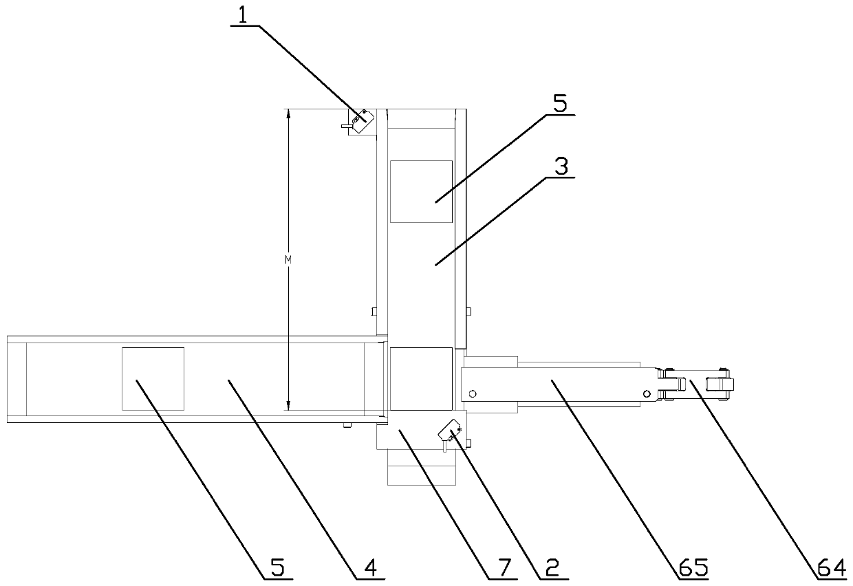
[0027] Such as figure 1 , a transfer control method, comprising the following steps,

[0028] A. The workpiece 5 is placed or transported to the first conveying device 3 and detected by the infrared sensor 1;

[0029] B. The conveying linear velocity V1 of the first conveying device 3 is set, and according to the conveying distance M on the first conveying device 3, the time S1 required for conveying a single workpiece 5 on the first conveying device 3 is obtained by calculating M / V1; figure 1 , the conveying distance is the linear distance between the top of the first conveying device and the abutment block;

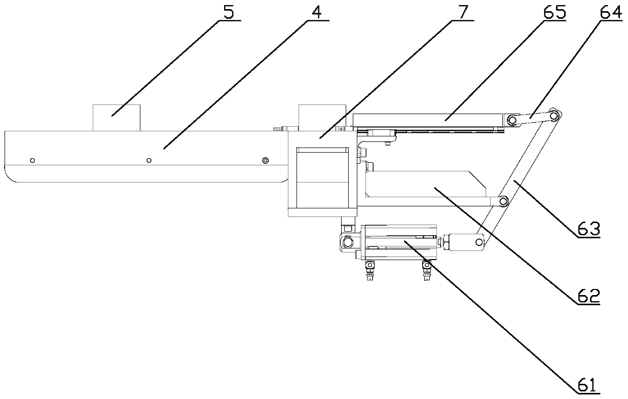
[0030] C, pushing assembly obtains the time interval of pushing the workpiece 5 according to the calculated time S1, which is the same as the value of S1; the pushing assembly of the present invention includes a cylinder 61, a fixed rod 62, a rotating rod 63, a driven rod 64 and push rod 65;

[0031] D. The controller controls the piston rod of the cylinder 61 to pus...


PUM


Abstract

The invention discloses a transporting conveying control method. The transporting conveying control method includes the steps that A, workpieces are placed and are detected by an infrared sensor; B, time S1 of each of the workpieces is conveyed on a first conveying device can be obtained by calculating M / V1; C, assemblies are pushed according to the calculated time S1, and time intervals of pushing the workpieces can be obtained; D, a piston rod of an air cylinder pushes a rotating rod to rotate around the fixing rod to the left, and then the rotating rod drives a driven rod to move to the left, the driven rod then pushes a pushing rod to move to the left in the direction of a sliding rail, and the moving distance of the pushing rod is larger than the width of the first conveying device; E, the piston rod of the air cylinder uses a leverage to drag the pushing rod to move to the left; and in the step D, the workpieces are pushed from the first conveying device to a second conveying device and are sent out. The transporting conveying control method is precise in control, the errors and the mistakes generated by a distance sensor can be reduced, and the transmission efficiency is improved.

Description

technical field [0001] The invention relates to the technical field of workpiece conveying. Background technique [0002] In the process of workpiece steering and transmission, the existing conveying mechanism is a mechanism that works continuously at a constant speed, and the blocking mechanism is a mechanism that works periodically reciprocatingly. Accumulation, blockage and other failures will lead to damage to the quality of the workpiece; when the failure is serious and cannot be solved in a short time, the front and back processes can only be forced to stop, resulting in a stagnation of production. [0003] Most of the existing conveying devices adopt the method of distance sensor sensing distance, which has the advantage of accurate distance sensing and less error prone. However, this method of detecting the position of the workpiece also has its disadvantages. If the shape of the workpiece is irregular, the distance sensed by the sensor will be deviated. In addition...

Claims


Application Information

Patent Timeline
Patent Type & Authority Patents(China)
IPC IPC(8): B65G43/08
CPCB65G43/08
Inventor 郑佳丹
Owner 重庆九仁杰智能装备科技有限公司
Learn More