Prefabricated concrete frame beam-column joint construction method

A technology for precast concrete, beam-column joints, applied in columns, joists, girders, etc., can solve the problems of cast-in-place concrete polluting the environment, low resource utilization, insufficient seismic performance, etc. , the effect of simple and quick connection

Active Publication Date: 2018-05-18
TIANJIN UNIV RES INST OF ARCHITECTRUAL DESIGN & URBAN PLANNING
View PDF5 Cites 25 Cited by
  • Summary
  • Abstract
  • Description
  • Claims
  • Application Information

AI Technical Summary

Problems solved by technology

[0002] At present, domestic housing construction is mainly cast-in-place concrete buildings, but cast-in-place concrete buildings pollute the environment, have low resource utilization rates, and cause serious waste, which conflicts with the national strategy of protecting the environment and saving resources.
In recent years, my country has been vigorously developing prefabricated buildings, and prefabricated buildings are booming. However, compared with cast-in-place buildings, prefabricated buildings have poor integrity and insufficient seismic performance. It is imperative to study reliable and excellent new connection nodes. Row
The current concrete frame beam-column joints mostly use sleeves, grout anchors, welding, etc., which requires a large amount of on-site work, inconvenient construction, and low efficiency

Method used


Image

  • Prefabricated concrete frame beam-column joint construction method
  • Prefabricated concrete frame beam-column joint construction method
  • Prefabricated concrete frame beam-column joint construction method

Examples


Embodiment Construction

[0022] In order to further understand the invention content, characteristics and effects of the present invention, the following examples are given, and detailed descriptions are as follows in conjunction with the accompanying drawings:

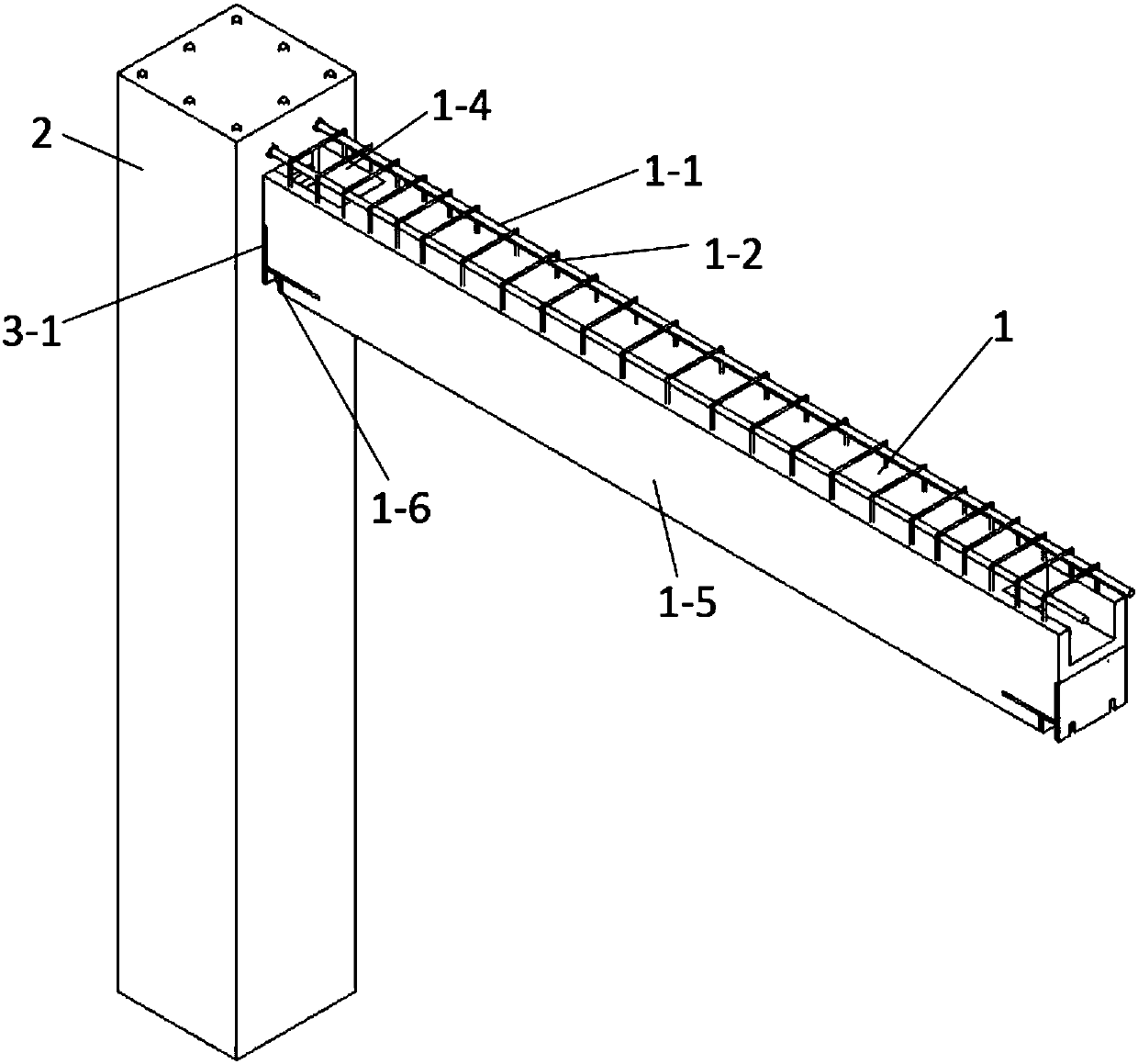
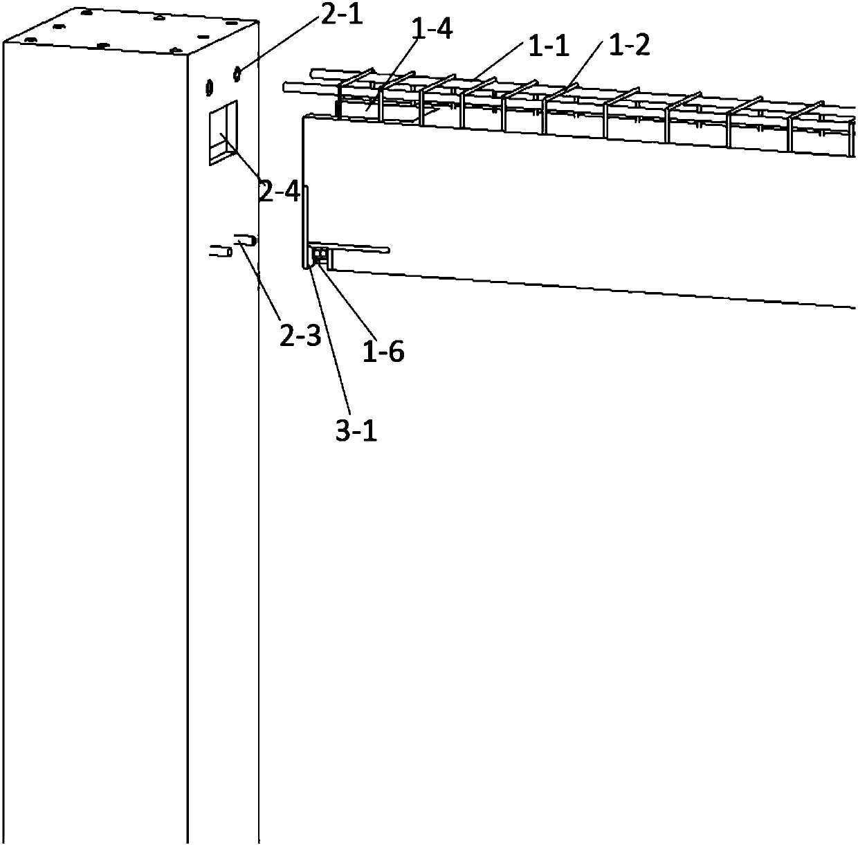
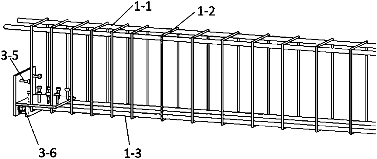
[0023] see Figure 1 to Figure 6 , a prefabricated concrete frame beam-column joint construction method, the frame column is a prefabricated column 2, adopts a reinforced concrete structure, the frame beam adopts a composite beam 1, and the composite beam 1 adopts a reinforced concrete structure, and is provided with prefabricated beams 1-5 and the post-casting part, the composite beam stirrup 1-2 protrudes above the top surface of the prefabricated beam 1-5, and a beam end keyway 1-4 is prefabricated on the upper part of the beam end of the prefabricated beam 1-5, A connection plate 3-1 is embedded in the lower part of the beam end of the prefabricated beam 1-5, and a connection installation groove 1-6 is prefabricated at the bottom of the b...


PUM


Abstract

The invention discloses a prefabricated concrete frame beam-column joint construction method, and relates to connection of a prefabricated column and a superposed beam. High-strength bolt bars and threaded sleeves are pre-buried in the column side of the prefabricated column, and a column side key groove is pre-formed; a beam end key groove is pre-formed in the beam end of a prefabricated beam, and a connection plate is pre-buried; the construction method adopts the following steps that (1), mounting of the prefabricated column is completed; (2) the prefabricated beam is mounted from top to bottom, so that the high-strength bolt rods penetrate through bolt connection holes; (3), upper longitudinal ribs of the superposed beam are mounted, firstly connection of the upper longitudinal ribs ofthe superposed beam and the threaded sleeves is completed, and then tying of the upper longitudinal ribs of the superposed beam and stirrups of the superposed beam is completed; (4) a washer and a lock nut are connected to each high-strength bolt rod to form pretightening force; and (5), templates are supported on the two sides of the prefabricated beam, concrete is poured, and a post-cast concrete anti-shear key integrated with a post-cast part of the superposed beam is formed in each of the beam end key groove and the column side key groove. The prefabricated concrete frame beam-joint construction method can achieve easy, rapid and convenient on-situ connection of the prefabricated column and the superposed beam, and connection is stable and reliable.

Description

technical field [0001] The invention relates to the field of construction, in particular to a construction method for prefabricated concrete frame beam-column joints. Background technique [0002] At present, domestic housing construction is mainly cast-in-place concrete buildings, but cast-in-place concrete buildings pollute the environment, have low utilization rate of resources, and cause serious waste, which conflicts with the national strategy of protecting the environment and saving resources. In recent years, my country has been vigorously developing prefabricated buildings, and prefabricated buildings are booming. However, compared with cast-in-place buildings, prefabricated buildings have poor integrity and insufficient seismic performance. It is imperative to study reliable and excellent new connection nodes. Row. The current concrete frame beam-column joints mostly use sleeves, slurry anchors, welding, etc., which requires a large amount of on-site work, inconveni...

Claims


Application Information

Patent Timeline
Patent Type & Authority Applications(China)
IPC IPC(8): E04G21/00E04B1/20E04B1/21E04C3/20E04C3/34
CPCE04B1/20E04B1/21E04C3/20E04C3/34E04G21/00
Inventor 张锡治段东超安海玉
Owner TIANJIN UNIV RES INST OF ARCHITECTRUAL DESIGN & URBAN PLANNING
Why Eureka
Try Eureka