Cooling system used for shaft system of wind generating set and wind generating set

A technology for wind turbines and cooling systems, applied in wind turbines, wind power generation, engines, etc., can solve problems affecting the life of lubricating grease, and achieve the effects of reliable installation, guaranteed service life, and simple implementation

Active Publication Date: 2018-05-18
BEIJING GOLDWIND SCI & CREATION WINDPOWER EQUIP CO LTD
View PDF7 Cites 16 Cited by
  • Summary
  • Abstract
  • Description
  • Claims
  • Application Information

AI Technical Summary

Problems solved by technology

Moreover, many failure forms of bearings are all caused by "heat" in the final analysis, and, with the gradual increase of wind turbine power generation, heat dissipation problems not only affect the life of grease, but also cause damage to other components of wind turbines. Threats (e.g., internal components that may melt due to high temperatures) are of increasing concern

Method used


Image

  • Cooling system used for shaft system of wind generating set and wind generating set
  • Cooling system used for shaft system of wind generating set and wind generating set
  • Cooling system used for shaft system of wind generating set and wind generating set

Examples


Embodiment Construction

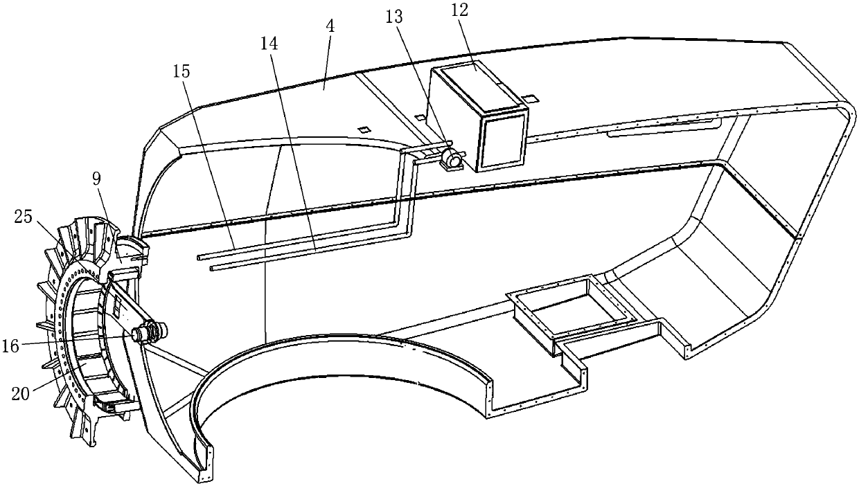
[0033] Embodiments of the present invention will be specifically described below in conjunction with the accompanying drawings. In the following, the main bearing of the wind power generating set will be described as the cooling object, but it should be noted that the present invention is not limited thereto, and the cooling system according to the exemplary embodiment can also be applied to other shafting of the wind power generating set.

[0034] image 3It is a partially cut-away and exploded schematic diagram of a wind power generating set including a cooling system for a wind power generator according to an embodiment of the present invention; Figure 4 is a partial structural schematic diagram of a cooling system according to an embodiment of the present invention; Figure 5 is a structural schematic diagram of a heat dissipation substrate according to an embodiment of the present invention.

[0035] Such as image 3 and Figure 4 As shown, the cooling system accordi...


PUM


Abstract

The invention provides a cooling system used for a shaft system of a wind generating set and the wind generating set. The cooling system comprises an annular radiating assembly fixedly installed on the inner surface of a rotating shaft, a cooling medium transmission assembly fixedly bonded with the annular radiating assembly, a fluid sliding ring assembly fixed to a fixed shaft and a condenser fixed to a part, except for the shaft system, of the wind generating set, and the cooling medium transmission assembly is connected with the condenser through the fluid sliding ring assembly to form a refrigerating cycle loop for dissipating heat transmitted from the shaft system to the annular radiating assembly. The cooling system is additionally arranged after the wind generating set is designed and completed, running of other components in the wind generating set is not influenced, implementation is simple, and installation is reliable; and in addition, a fluid sliding ring is arranged between a dynamic part and a static part, fluid communication between the dynamic part and the static part is achieved, and circulation of the cooling system is achieved.

Description

technical field [0001] The invention relates to the field of wind power generation, in particular to a cooling system for a shaft system of a wind power generating set. Background technique [0002] Most wind turbines use permanent magnet direct drive wind turbines, such as figure 1 (Schematic diagram of the structure of a wind turbine) and figure 2 ( figure 1 As shown in the sectional view of part A of ), the wind turbine with permanent magnet direct drive wind generator mainly includes: blade 1, hub 2, generator subsystem 3, nacelle 4 and tower 5. The generator subsystem 3 mainly includes: a permanent magnet direct drive wind turbine 6, a fixed shaft 7, a rotating shaft 9, and a main bearing. The main bearing includes a bearing inner ring 10, a bearing roller 8 and a bearing outer ring 11. The bearing inner ring 10 is connected to the rotating shaft 9, and the bearing outer ring 11 is connected to the fixed shaft 7. Since the blade 1 and the wheel hub 2 are connected t...

Claims


Application Information

Patent Timeline
Patent Type & Authority Applications(China)
IPC IPC(8): F03D80/60F03D80/70
CPCF03D80/60F03D80/70Y02E10/72
Inventor 高杨方涛梁坤峰方志祥
Owner BEIJING GOLDWIND SCI & CREATION WINDPOWER EQUIP CO LTD
Why Eureka
Try Eureka