Combustion furnace based on liquid ethanol-natural gas composite fuel and method thereof

A combustion furnace and natural gas technology, which is applied to the combustion of liquid fuel and gaseous fuel, the combustion of block fuel and liquid fuel, the combustion of liquid fuel and powder fuel, etc. Emission, inability to adapt to liquid ethanol fuel, high working temperature and other problems, to achieve the effect of simple structure, uniform heating and sufficient heating

Active Publication Date: 2018-05-18
谢丽萍
View PDF5 Cites 29 Cited by
  • Summary
  • Abstract
  • Description
  • Claims
  • Application Information

AI Technical Summary

Problems solved by technology

[0002] The heat-conducting oil boiler uses heat-conducting oil as the medium, and uses the hot oil circulating oil pump to force the medium to circulate in liquid phase, transfer the heat energy to the heat-consuming equipment and then return to the heating furnace for reheating, and deliver the heat energy to the heat-consuming equipment before returning to the heating furnace for reheating , it can obtain high working temperature under low pressure, and can carry out high-precision control work on the operation of the medium; the combustion chamber of the existing heat-conducting oil boiler is mainly composed of simple combustion-supporting air and gas mixed and sprayed into the combustion chamber, due to The normal injection flame cannot completely and evenly heat the heating tube in the existing regular cylindrical combustion chamber, resulting in full use of heat, and at the same time, some gas is not fully utilized and is discharged with the flue gas, resulting in energy waste;
[0003] At the same time, the existing combustion furnace uses a single gas fuel, but ethanol is a liquid renewable energy source. Due to the liquid property, the existing combustion furnace combustion chamber structure cannot adapt to liquid ethanol fuel.

Method used


Image

  • Combustion furnace based on liquid ethanol-natural gas composite fuel and method thereof
  • Combustion furnace based on liquid ethanol-natural gas composite fuel and method thereof
  • Combustion furnace based on liquid ethanol-natural gas composite fuel and method thereof

Examples


Embodiment Construction

[0030] The present invention will be further described below in conjunction with the accompanying drawings.

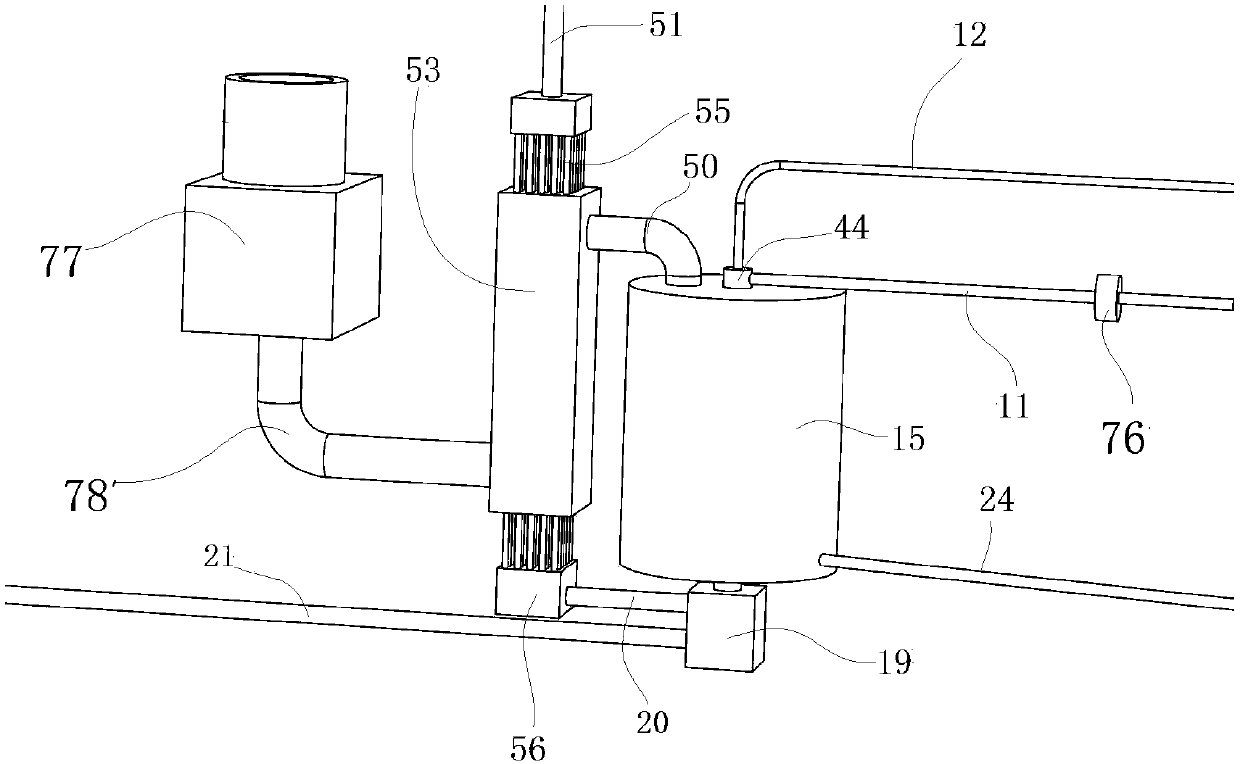
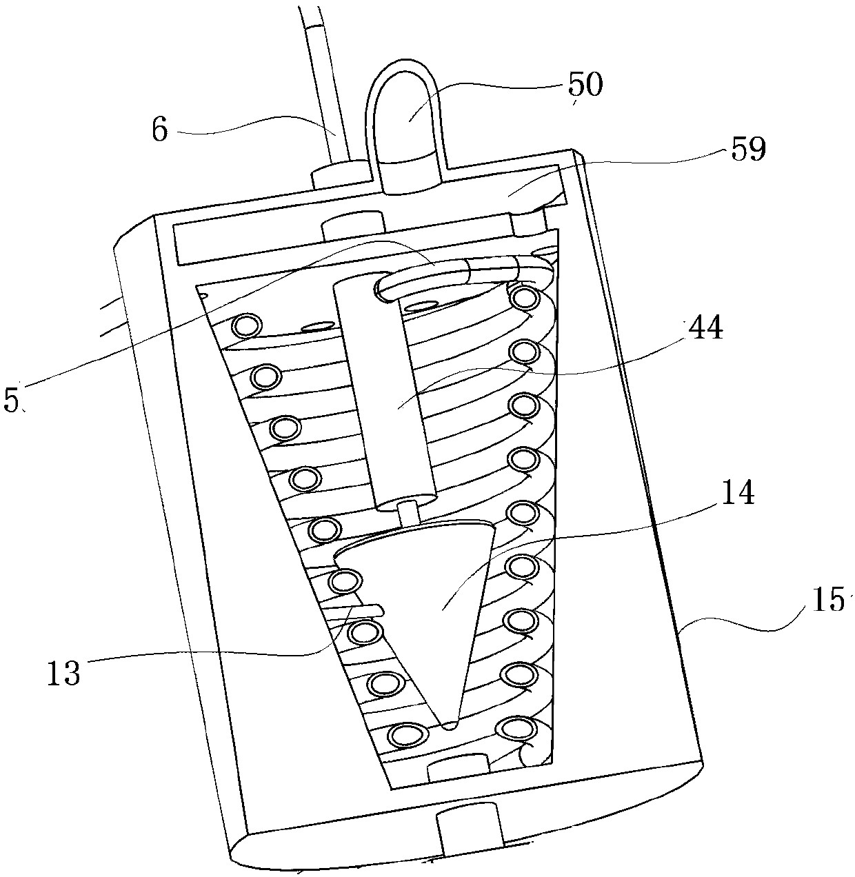
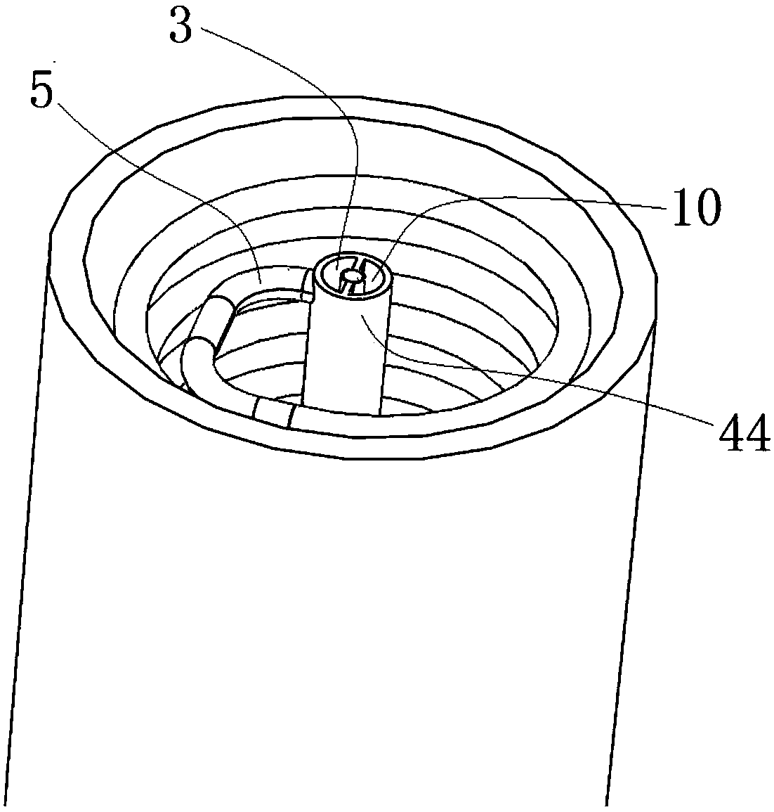
[0031] as attached Figures 1 to 7A kind of combustor based on liquid ethanol-natural gas combined fuel shown comprises a combustor body 15, and the combusted fuel combustor 17 is included in the combustor body 15, and in this embodiment, the combusted fuel combustor 17 has a thin end facing downward The conical circular frustum structure; the lower end of the combined fuel combustion chamber 17 is coaxially provided with a flame nozzle 7, and the flame injection direction of the flame nozzle 7 is vertically upward; the upper end of the combined fuel combustion chamber 17 is a smoke exhaust wall 60, and the A number of smoke outlets 27 are arranged on the smoke exhaust wall 60; the combined fuel combustion chamber 17 also includes an ethanol gasification cone 14; the outer wall of the ethanol gasification cone 14 is a conical structure with the tip facing downward; Th...


PUM


Abstract

The invention discloses a combustion furnace based on liquid ethanol-natural gas composite fuel. The combustion furnace comprises a combustion furnace body, and the combustion furnace body comprises acomposite fuel combustion furnace which is of a cone-shaped circular platform structure with a thin end facing down; the lower end of the composite fuel combustion furnace is coaxially provided witha flame nozzle, and the firing direction of the flame nozzle is vertical upwards; the upper end of the composite fuel combustion furnace is a smoke exhaust wall, and the smoke exhaust wall is providedwith a plurality of smoke outlets; and the combustion furnace is simple in structure, the cone-shaped circular platform type combustion chamber is adopted and matched with an ethanol gasification cone to guide ordinary natural gas jet flames into a trumpet shape, and the flames go forwards by being attached to a heating pipe distributed in a conical spiral form, so that the heating area of the flames is enlarged.

Description

technical field [0001] The invention belongs to the field of combustion furnaces, in particular to a combustion furnace based on liquid ethanol-natural gas combined fuel and a method thereof. Background technique [0002] The heat-conducting oil boiler uses heat-conducting oil as the medium, and uses the hot oil circulating oil pump to force the medium to circulate in liquid phase, transfer the heat energy to the heat-consuming equipment and then return to the heating furnace for reheating, and deliver the heat energy to the heat-consuming equipment before returning to the heating furnace for reheating , it can obtain high working temperature under low pressure, and can carry out high-precision control work on the operation of the medium; the combustion chamber of the existing heat-conducting oil boiler is mainly composed of simple combustion-supporting air and gas mixed and sprayed into the combustion chamber, due to The normal injection flame cannot completely and evenly h...

Claims


Application Information

Patent Timeline
Patent Type & Authority Applications(China)
IPC IPC(8): F23C1/08F23C3/00F23C5/32F23C7/00F23K5/00F23K5/22F23L15/04F24H7/02F24H9/18
CPCF23C1/08F23C3/00F23C5/32F23C7/00F23K5/002F23K5/22F23L15/045F24H7/0266F24H9/1836Y02E20/34
Inventor 崔秀萍
Owner 谢丽萍
Why Eureka
Try Eureka