Temperature measurement device for bus duct

A technology of temperature measuring device and bus duct, which is applied in the field of bus duct, can solve the problems of safety and quality accidents, abnormal overheating of bus joint temperature, fire, etc., and achieves the effects of no electromagnetic interference, wide application range and high safety.

Pending Publication Date: 2018-05-18
南通市盈思仪器科技有限公司
View PDF0 Cites 3 Cited by
  • Summary
  • Abstract
  • Description
  • Claims
  • Application Information

AI Technical Summary

Problems solved by technology

[0003] However, in the actual application of the busway, due to the long-term operation in the air and the influence of the ambient temperature and humidity, there will be thermal expansion and contraction, surface scaling, oxidation or corrosion, resulting in loose contacts and poor contact, especially in some large In buildings (such as large factory buildings, super high-rise buildings, etc.), the installation position of the bus duct cannot be monitored manually, and the user often ignores the safety management of the bus duct. Once the temperature of the bus joint in operation is abnormally overheated, it may cause a fire. Or major safety and quality accidents, bringing huge and irreparable personal casualties and economic and property losses to the enterprise
[0004] The bus duct is in a fully closed state during operation, and is generally in a long-term electrified state. It is very inconvenient for daily maintenance and inspection. Therefore, it is necessary to monitor the temperature of the bus joints in the bus duct to improve the reliability of the bus duct operation.
[0005] With the continuous development of technology, various wireless busbar temperature measuring devices are used in the daily maintenance of the busbar, basically using battery power supply, solar power supply, external power supply, self-inductance power supply, etc., the device structure is complex

Method used


Image

  • Temperature measurement device for bus duct
  • Temperature measurement device for bus duct
  • Temperature measurement device for bus duct

Examples


Embodiment Construction

[0038] The application will be further described in detail below in conjunction with the accompanying drawings and embodiments. It should be understood that the specific embodiments described here are only used to explain related inventions, rather than to limit the invention. It should also be noted that, for ease of description, only parts related to the invention are shown in the drawings.

[0039] It should be noted that, in the case of no conflict, the embodiments in the present application and the features in the embodiments can be combined with each other. The present application will be described in detail below with reference to the accompanying drawings and embodiments.

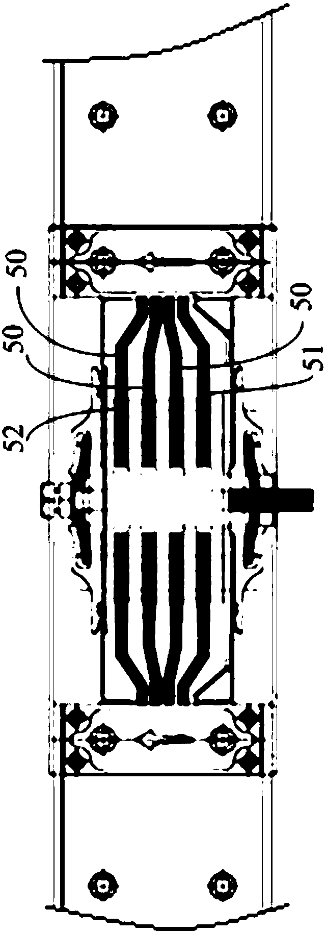
[0040] Please refer to figure 1 The schematic diagram of the structure of the bus duct proposed by the embodiment of the present invention is shown. A pair of bus joints are arranged in the bus duct. The bus joints include three conductive bars 50 for live lines and one conductive bar 51 for neutr...


PUM


Abstract

The invention discloses a temperature measurement device for a bus duct. The device comprises a shell, a temperature measurement circuit board in the shell and multiple temperature sensors which are connected with the temperature measurement circuit board; a column is further connected to the temperature measurement circuit board and comprises a first conductive column body which is in contact with a fire line conducting bar and a second conductive column body which is in contact with a null line conducting bar. According to the temperature measurement device for the bus duct, electricity is taken from a bus itself through the first column body and the second column body, so that the whole temperature measurement device has stable power supply, and the structure is extremely simple.

Description

technical field [0001] The present disclosure generally relates to the field of bus duct technology, and in particular to a bus duct temperature measuring device. Background technique [0002] Since the busway was introduced into our country in the late 1980s, it has developed rapidly in more than 20 years. Among them, low-voltage busway has become an important branch of power distribution equipment due to its large carrying current and strong applicability, and is widely used in various industries. [0003] However, in the actual application of the busway, due to the long-term operation in the air and the influence of the ambient temperature and humidity, there will be thermal expansion and contraction, surface scaling, oxidation or corrosion, resulting in loose contacts and poor contact, especially in some large In buildings (such as large factory buildings, super high-rise buildings, etc.), the installation position of the bus duct cannot be monitored manually, and the u...

Claims


Application Information

Patent Timeline
IPC IPC(8): G01K13/00G01K1/14
CPCG01K1/14G01K13/00
Inventor 邓勇
Owner 南通市盈思仪器科技有限公司
Why Eureka
Try Eureka