Glass-fiber cement concrete compression strength test mold and use method
A technology of cement concrete and glass fiber, which is applied in the field of glass fiber cement concrete compressive strength test mold, can solve the problems of less rigidity than steel test mold, poor stability, easy damage, etc., and achieve light weight, good plasticity and good stability Effect
- Summary
- Abstract
- Description
- Claims
- Application Information
AI Technical Summary
Problems solved by technology
Method used
Image

Examples
Embodiment 1
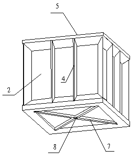
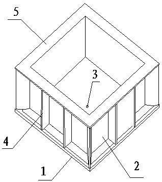
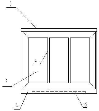
[0034] A kind of glass fiber cement concrete compressive strength test form, its composition comprises: glass fiber test form bottom plate 1 and glass fiber test form side plate 2, described glass fiber test form side plate is arranged on described glass fiber test form bottom plate above, and the middle position of the glass fiber trial mold base plate is provided with a demoulding hole 3, and the outside of the glass fiber trial mold side plate is connected at right angles to the two adjacent glass fiber trial mold side plates A stiffener plate A4 is provided at the position, the upper part of the glass fiber trial mold side plate is connected with a square frame 5 structure, one end of the stiffener plate A is connected with the bottom of the square frame, and the other end is connected with the square frame. The upper part of the fiberglass test mold bottom plate is connected, and a square groove 6 is provided below the glass fiber trial mold bottom plate, and a bottom plat...
Embodiment 2
[0036] According to the glass fiber cement concrete compressive strength test mold described in embodiment 1, described glass fiber base plate, described glass fiber test mold side plate, described stiffener plate A, described stiffener plate B, The bottom slab ribs, the square frame and the buckle are integrally cast, and the above structures together form a glass fiber cement concrete compressive strength test mold.
Embodiment 3
[0038] According to the glass fiber cement concrete compressive strength test mold described in embodiment 1 or 2, the height of the described glass fiber test mold side plate is 150mm, and the width is 150mm, and the width of the described square frame is 182mm, and the height is 7mm , the length of the bottom plate of the fiberglass test mold is 182mm, the height is 10mm, and the depth of the square groove is 4mm.
PUM
| Property | Measurement | Unit |
|---|---|---|
| Height | aaaaa | aaaaa |
| Width | aaaaa | aaaaa |
| Width | aaaaa | aaaaa |
Abstract
Description
Claims
Application Information
 - R&D
- Intellectual Property
- Life Sciences
- Materials
- Tech Scout
- Unparalleled Data Quality
- Higher Quality Content
- 60% Fewer Hallucinations
Browse by: Latest US Patents, China's latest patents, Technical Efficacy Thesaurus, Application Domain, Technology Topic, Popular Technical Reports.
© 2025 PatSnap. All rights reserved.Legal|Privacy policy|Modern Slavery Act Transparency Statement|Sitemap|About US| Contact US: help@patsnap.com