
A non-contact all-optical photoacoustic imaging device and method thereof

A photoacoustic imaging, non-contact technology, applied in the direction of measuring devices, material analysis through optical means, scientific instruments, etc., can solve the problems of local defocus, imaging quality impact, resolution deterioration, etc., to improve imaging speed Effect

Active Publication Date: 2021-02-12
SOUTH CHINA NORMAL UNIVERSITY
View PDF3 Cites 0 Cited by
  • Summary
  • Abstract
  • Description
  • Claims
  • Application Information

AI Technical Summary

Problems solved by technology

However, when the surface of the detected object has large fluctuations, the optical path difference between the sample arm and the reference arm will exceed the coherence length of the detection light, and there will be no interference signal at this time, that is, no photoacoustic signal can be detected
At the same time, after the traditional Gaussian light is focused by the objective lens, its focal length is generally several microns, so it cannot maintain good lateral resolution in the larger depth direction
Therefore, when the surface flatness of the sample to be inspected is not good, local defocusing will occur during the two-dimensional scanning process, resulting in poor resolution and negative impact on imaging quality.

Method used


Image

  • A non-contact all-optical photoacoustic imaging device and method thereof
  • A non-contact all-optical photoacoustic imaging device and method thereof
  • A non-contact all-optical photoacoustic imaging device and method thereof

Examples


Embodiment 1

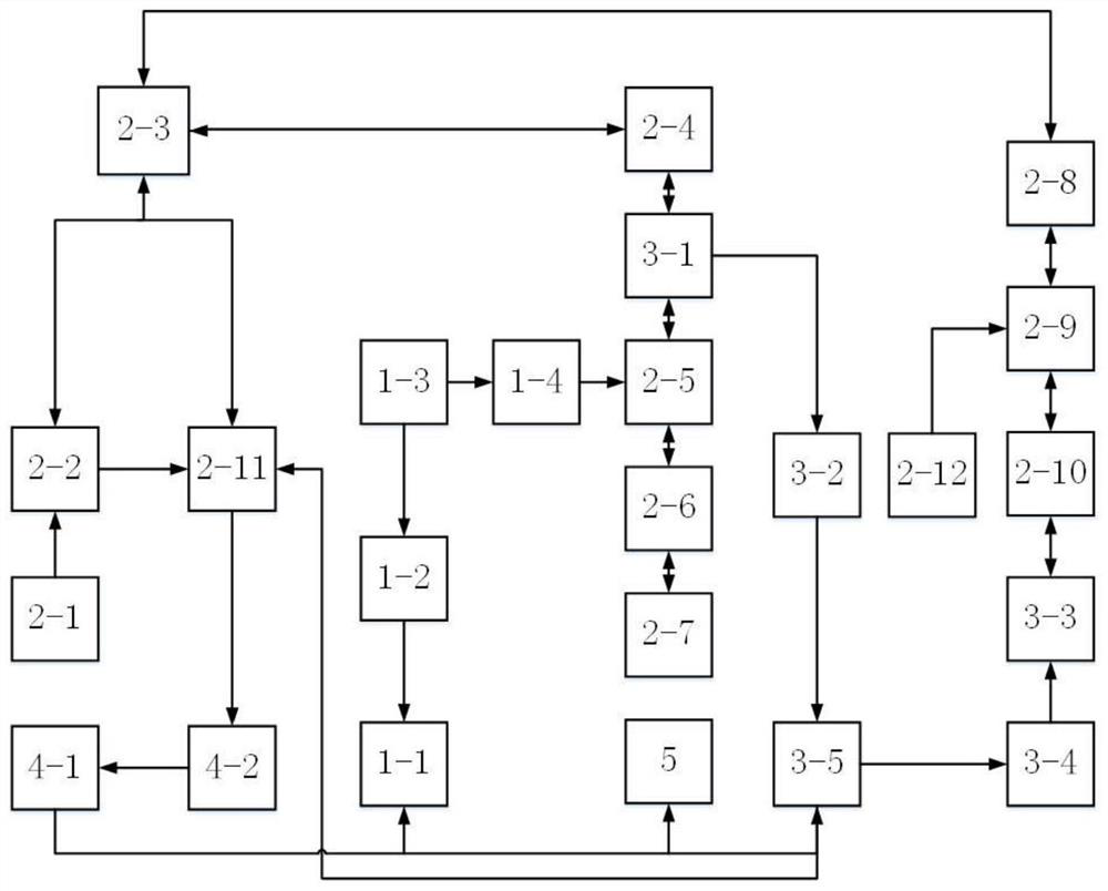
[0037] Such as figure 1 As shown, a non-contact all-optical photoacoustic imaging device includes a photoacoustic signal excitation component, a photoacoustic signal detection component, an interferometric phase modulation component, a photoacoustic signal acquisition / processing component, and a scanning platform. The photoacoustic signal The excitation component, the photoacoustic signal detection component, the interferometric phase modulation component and the photoacoustic signal acquisition / processing component are connected in sequence, the photoacoustic signal acquisition / processing component is respectively connected to the photoacoustic signal excitation component, the photoacoustic signal detection component, the interferometric phase modulation component and the photoacoustic signal The signal detection component is connected, and the scanning platform is respectively connected with the photoacoustic signal excitation component and the photoacoustic signal detection ...

Embodiment 2

[0057] Using the non-contact all-optical photoacoustic imaging device and method of Embodiment 1 includes the following steps:

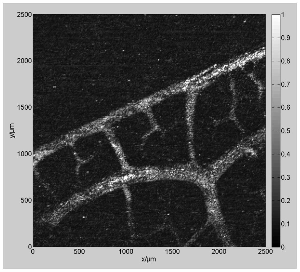
[0058] (1) Embedding the veins in the agar with a concentration of 1%, smearing a thin layer of mineral oil on the surface of the agar, and fixing the simulated sample on the sample stage, and adjusting the height;

[0059] (2) The photoacoustic signal excitation light source and the photoacoustic signal detection light source are turned into coaxial light beams by dichroic mirrors, and then focus on the upper surface of the agar block after passing through the beam expander and axicon lens. Adjust the displacement platform of the reference arm so that the reference beam The optical path difference between the arm and the sample arm is zero, that is, the photoacoustic signal detection light interferes;

[0060] (3) The excitation light of the photoacoustic signal is irradiated on the surface of the agar block, and the veins inside the agar block abso...


PUM

PropertyMeasurementUnit
wavelengthaaaaaaaaaa

Abstract

The invention discloses a non-contact all-optical photoacoustic imaging device and a method thereof. The device includes a photoacoustic signal excitation component, a photoacoustic signal detection component, an interference phase modulation component, a photoacoustic signal acquisition / processing component, and a scanning platform. The acoustic signal excitation component, the photoacoustic signal detection component, the interferometric phase modulation component and the photoacoustic signal acquisition / processing component are connected in sequence, the photoacoustic signal acquisition / processing component is respectively connected to the photoacoustic signal excitation component, the photoacoustic signal detection component, and the interferometric phase modulation component The scanning platform is respectively connected with the photoacoustic signal excitation component and the photoacoustic signal detection component. The invention utilizes pulsed laser to irradiate biological samples to generate photoacoustic signals, and uses a narrow-linewidth superluminescent diode continuous light source as a photoacoustic signal detection light source to improve the detection sensitivity of samples with insufficiently flat surfaces, which is of great significance to the realization of the clinical application of photoacoustic technology. impetus.

Description

technical field [0001] The invention belongs to the technical field of photoacoustic imaging, and in particular relates to a non-contact all-optical photoacoustic imaging device and a method thereof. Background technique [0002] When a short-pulse laser is irradiated into a tissue, the tissue thermally expands due to the absorption of laser energy, and an ultrasonic signal is generated. This phenomenon is called the photoacoustic effect. Photoacoustic imaging technology is a newly developed biomedical imaging technology. It uses the principle of photoacoustic effect to combine the high contrast characteristics of pure optical imaging and the high penetration depth characteristics of pure ultrasonic imaging. Advantages such as ionization effect are gradually becoming a research hotspot in the field of nondestructive testing of biological tissues. In recent years, it has received more and more attention and research from scholars at home and abroad, and various photoacoustic...

Claims


Application Information

Patent Timeline
Patent Type & Authority Patents(China)
IPC IPC(8): G01N21/17
CPCG01N21/1702G01N2021/1706
Inventor 陈重江胡毅成杨思华邢达
Owner SOUTH CHINA NORMAL UNIVERSITY
Learn More