Imaging optical system

An imaging optics and imaging technology, applied in optics, optical components, instruments, etc., to achieve the effects of extended applicability, good imaging quality, and low difficulty in installation and adjustment

Active Publication Date: 2018-05-18
CHANGCHUN INST OF OPTICS FINE MECHANICS & PHYSICS CHINESE ACAD OF SCI
View PDF3 Cites 3 Cited by
  • Summary
  • Abstract
  • Description
  • Claims
  • Application Information

AI Technical Summary

Problems solved by technology

[0004] The present invention aims to overcome the restriction of the dynamic range of the existing image sensor on the detection dynamic range of the photoelectric system, and provide an imaging optical system that meets the requirements for scene measurement and observation of high dynamic radiation energy characteristics

Method used


Image

  • Imaging optical system
  • Imaging optical system
  • Imaging optical system

Examples


Embodiment 1

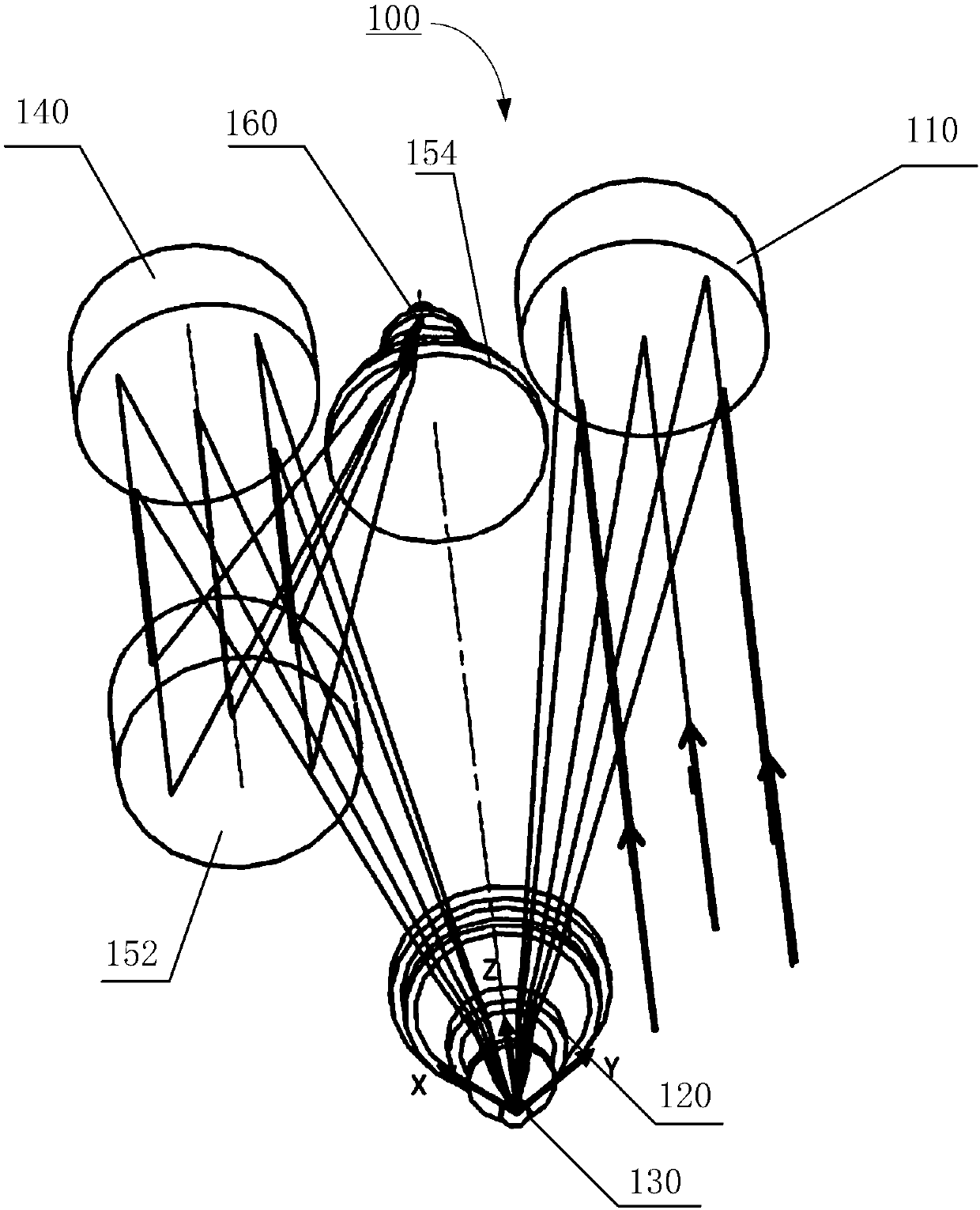
[0046] In this embodiment, the size of the DMD micromirror array 130 is selected to be 1920×1080, and the size of a single micromirror is 10.8 μm. The resolution of the detector 160 is selected to be 1920×1080, and the pixel size is 10.8 μm. A catadioptric imaging optical system 100 with a long focal length and a small relative aperture is designed, and the operating wavelength is the visible light band. The system parameters are shown in Table 1. This imaging optical system 100 can be regarded as being made up of two parts, and the first part is the telescopic system that magnification is-1, by the first off-axis mirror 110, the first lens group 120, the DMD micromirror array 130, the second off-axis The second part is a secondary imaging system, which is composed of an imaging mirror group and a detector 160.

[0047] The design of the imaging optical system in this embodiment is as follows figure 1 and figure 2 As shown, following the right-handed coordinate rule, the Z-...

Embodiment 2

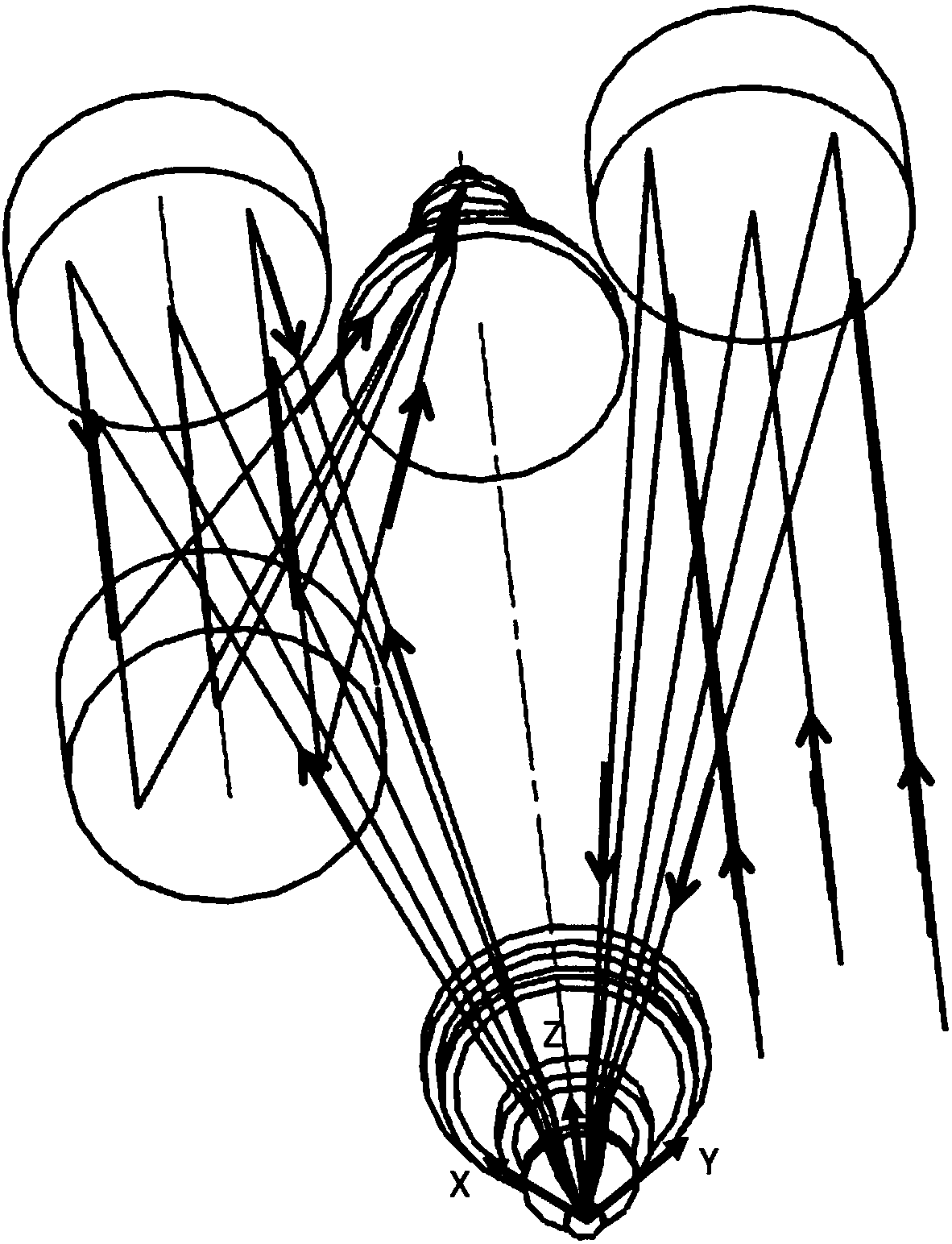
[0053] In this embodiment and embodiment 1, the same DMD micromirror array 230 and detector 260 are selected, and the parameters of the imaging optical system 200 are the same as those in embodiment 1, see Table 1. The secondary imaging system uses a coaxial catadioptric structure, which is different from Embodiment 1. This shows that the DMD micromirror array is replaceable as the imaging mirror group in the imaging optical system of the intermediate image plane to meet different application requirements.

[0054] The design of the imaging optical system 200 in this embodiment is as follows Figure 6 As shown, following the right-handed coordinate rule, the Z-axis is the system optical axis and coincides with the base normal of the DMD micromirror array 230 . The light incident direction is parallel to the Z axis and points in the positive direction.

[0055] The light emitted by the target object is converged by the first off-axis mirror 210 , enters the first lens group 22...


PUM


Abstract

The invention relates to the technical field of optical imaging, and discloses an imaging optical system. The imaging optical system includes a first off-axis reflector, a first battery of lens, a DMDmicromirror array, a second off-axis reflector, an imaging mirror group and a detector, wherein the light emitted from the target object is converged through the first off-axis reflector, then entersthe first battery of lens, and then is imaged on the DMD micromirror array; and the imaging beam is reflected by the DMD micromirror array, then passes by the first battery of lens again, then entersin the imaging mirror group after being collimated by the second off-axis reflector, and then is imaged on the detector. The imaging optical system utilizes DMD as the intermediate image plane and the partially symmetrical optical structure design to skillfully realize the one-to-one corresponding relationship of the DMD micromirror array and the detector pixels so as to process the entrance light of the imaging system. The imaging optical system utilizes the corresponding imaging relationship of the DMD device and the detector pixels, thus being able to adjust the gray scale of the detectortarget surface so as to expand the dynamic range of the photoelectric imaging system.

Description

technical field [0001] The invention relates to the technical field of optical imaging, in particular to an imaging optical system. Background technique [0002] DMD is a popular spatial light modulator in recent years, mainly used in optical systems such as projectors and target generators. The DMD modulates the light intensity by controlling the flipping of millions of micromirrors on it, and each micromirror can be individually controlled. The state of the micromirror can be controlled by changing the data in the data unit corresponding to the micromirror. [0003] As a main optoelectronic imaging device, the image sensor has a detectable dynamic range of 48-60dB, which is the main factor restricting the detection range of the optoelectronic imaging system. High dynamic range imaging technology has an urgent demand in deep space exploration, medical imaging, military observation and other fields. Usually, the software processing method of multiple exposures or the hard...

Claims


Application Information

Patent Timeline
Patent Type & Authority Applications(China)
IPC IPC(8): G02B17/08
Inventor 何锋赟赵楠王延杰
Owner CHANGCHUN INST OF OPTICS FINE MECHANICS & PHYSICS CHINESE ACAD OF SCI
Why Eureka
Try Eureka