An imaging optical system
An imaging optics and imaging technology, applied in optics, optical components, instruments, etc., to expand the dynamic range of detection, meet the needs of measurement and observation of scenes with high dynamic radiant energy characteristics, and achieve good imaging quality.
- Summary
- Abstract
- Description
- Claims
- Application Information
AI Technical Summary
Problems solved by technology
Method used
Image
Examples
Embodiment 1
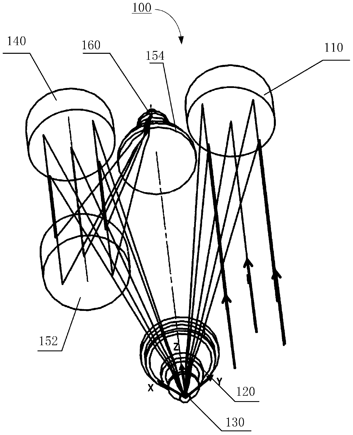
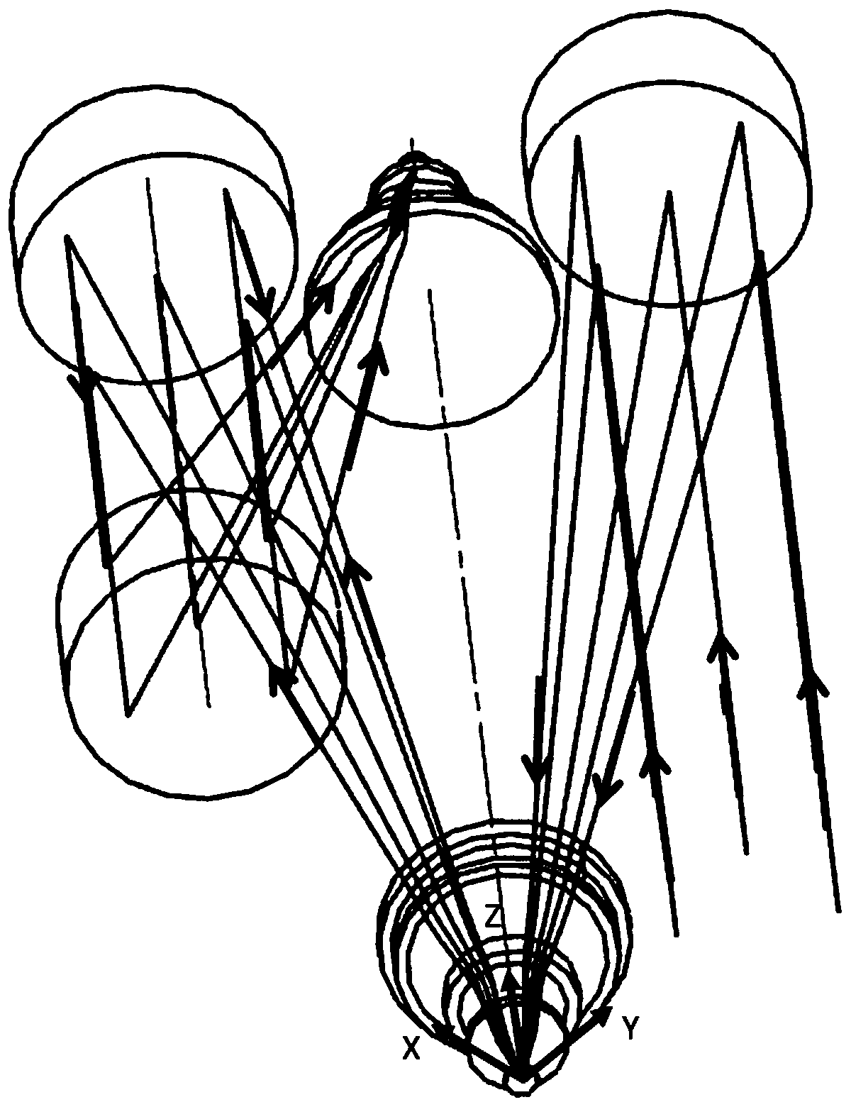
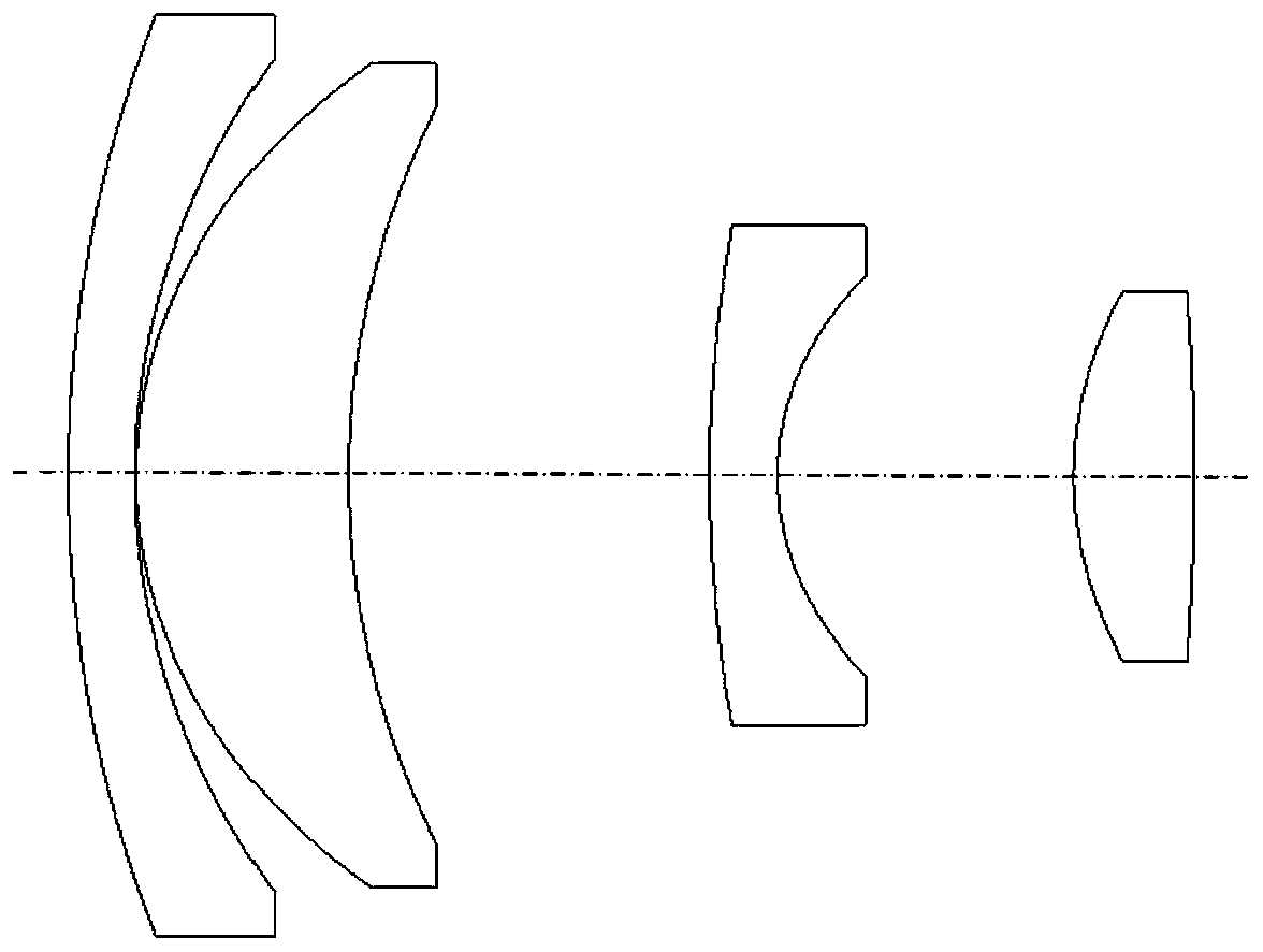
[0046] In this embodiment, the size of the DMD micromirror array 130 is selected to be 1920×1080, and the size of a single micromirror is 10.8 μm. The resolution of the detector 160 is selected to be 1920×1080, and the pixel size is 10.8 μm. A catadioptric imaging optical system 100 with a long focal length and a small relative aperture is designed, and the operating wavelength is the visible light band. The system parameters are shown in Table 1. This imaging optical system 100 can be regarded as being made up of two parts, and the first part is the telescopic system that magnification is-1, by the first off-axis mirror 110, the first lens group 120, the DMD micromirror array 130, the second off-axis The second part is a secondary imaging system, which is composed of an imaging mirror group and a detector 160.
[0047] The design of the imaging optical system in this embodiment is as follows figure 1 and figure 2 As shown, following the right-handed coordinate rule, the Z-...
Embodiment 2
[0053] In this embodiment and embodiment 1, the same DMD micromirror array 230 and detector 260 are selected, and the parameters of the imaging optical system 200 are the same as those in embodiment 1, see Table 1. The secondary imaging system uses a coaxial catadioptric structure, which is different from Embodiment 1. This shows that the DMD micromirror array is replaceable as the imaging mirror group in the imaging optical system of the intermediate image plane to meet different application requirements.
[0054] The design of the imaging optical system 200 in this embodiment is as follows Figure 6 As shown, following the right-handed coordinate rule, the Z-axis is the system optical axis and coincides with the base normal of the DMD micromirror array 230 . The light incident direction is parallel to the Z axis and points in the positive direction.
[0055] The light emitted by the target object is converged by the first off-axis mirror 210 , enters the first lens group 22...
PUM
 Abstract
Description
Claims
Application Information
 - R&D
- Intellectual Property
- Life Sciences
- Materials
- Tech Scout
- Unparalleled Data Quality
- Higher Quality Content
- 60% Fewer Hallucinations
Browse by: Latest US Patents, China's latest patents, Technical Efficacy Thesaurus, Application Domain, Technology Topic, Popular Technical Reports.
© 2025 PatSnap. All rights reserved.Legal|Privacy policy|Modern Slavery Act Transparency Statement|Sitemap|About US| Contact US: help@patsnap.com


