
Low-thermal-resistance substrate preparation process

A technology of substrate preparation and low thermal resistance, applied in printed circuit parts, chemical/electrolytic removal of conductive materials, formation of conductive patterns, etc., can solve the problem of poor thermal conductivity, insufficient thermal conductivity of copper plates, and unsatisfactory LED junction temperature. Reliability requirements and other issues, to achieve the effect of low thickness, reduced thermal resistance, and thin overall thickness

Inactive Publication Date: 2018-05-18
惠州瑞捷科技有限公司
View PDF3 Cites 0 Cited by
  • Summary
  • Abstract
  • Description
  • Claims
  • Application Information

AI Technical Summary

Problems solved by technology

However, as the power of electronic components is increasing and the heat generated is getting higher and higher, the junction temperature of LEDs using conventional substrates as circuit boards is getting higher and higher. Because of poor thermal conductivity, it often cannot meet the junction temperature requirements of LEDs. reliability requirements
In recent years, a structure with a copper plate or a flat heat pipe sandwiched between the upper and lower substrates has appeared on the market. The heat is transferred from the components that need to be dissipated to the substrate, and then transferred from the substrate to the interlayer of the copper plate or heat pipe, and then the interlayer It is transferred to the radiator, and the radiator exchanges heat with the external air to complete the heat dissipation process. However, due to the thickness requirements of the substrate, copper plate and flat heat pipe, the prepared product cannot meet the optical design requirements, and the copper plate As an interlayer, the thermal conductivity of the copper plate is not good enough, which leads to the fact that the LED junction temperature cannot meet the reliability requirements

Method used


Image

  • Low-thermal-resistance substrate preparation process
  • Low-thermal-resistance substrate preparation process
  • Low-thermal-resistance substrate preparation process

Examples


Embodiment 1

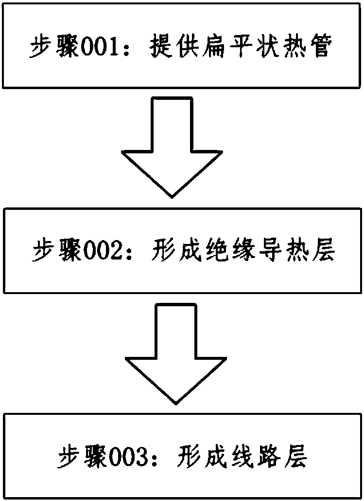
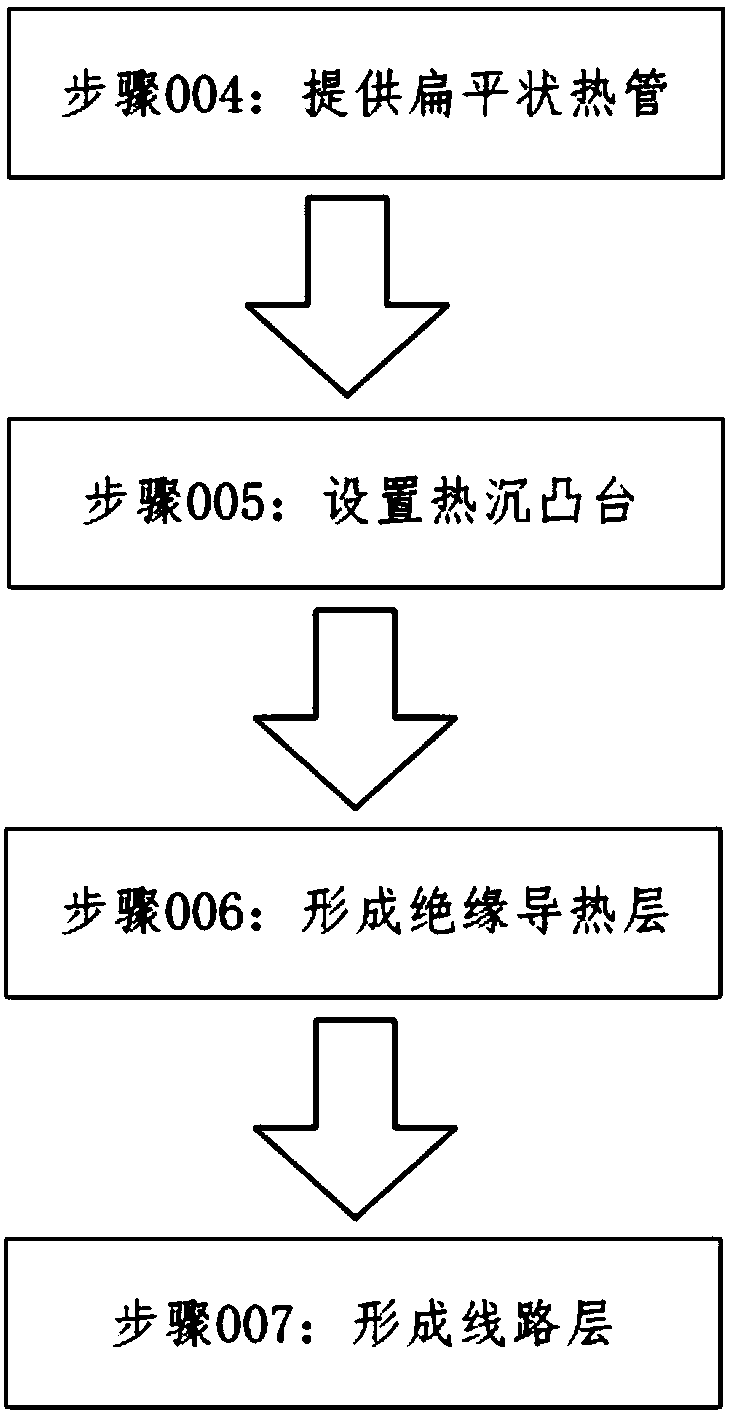
[0053] Provided is a flat heat pipe. The surface of the heat pipe is coated with epoxy resin, and an insulating heat conduction layer is formed on the surface of the heat pipe after the epoxy resin is cured.

[0054] Use conductive silver paste as the material of the circuit layer.

[0055] The circuit pattern is screen-printed on the surface of the insulating and heat-conducting layer by screen printing. In the screen printing, a 70-degree polyester screen is used to bake the conductive silver paste printed on the surface of the insulating and heat-conducting layer under infrared rays. The baking temperature is temperature at 150°C until the conductive silver paste solidifies and a circuit layer is formed on the surface of the insulating and heat-conducting layer.

[0056] Through the above steps, the low thermal resistance substrate of the present invention is obtained.

[0057] The low thermal resistance substrate manufactured by the low thermal resistance substrate prepar...

Embodiment 2

[0059] A flat heat pipe is provided. Polyimide resin is coated on the surface of the heat pipe, and the polyimide resin is cured to form an insulating heat conducting layer on the surface of the heat pipe.

[0060] Use conductive silver paste as the material of the circuit layer.

[0061] The circuit pattern is screen-printed on the surface of the insulating and heat-conducting layer by screen printing. In the screen printing, a 70-degree polyester screen is used to bake the conductive silver paste printed on the surface of the insulating and heat-conducting layer under infrared rays. The baking temperature is temperature at 150°C until the conductive silver paste solidifies and a circuit layer is formed on the surface of the insulating and heat-conducting layer.

[0062] Through the above steps, the low thermal resistance substrate of the present invention is obtained.

[0063] The low thermal resistance substrate manufactured by the low thermal resistance substrate preparat...

Embodiment 3

[0065] Provided is a flat heat pipe. The surface of the heat pipe is coated with epoxy resin, and an insulating heat conduction layer is formed on the surface of the heat pipe after the epoxy resin is cured.

[0066] Copper foil is used as the material of the wiring layer.

[0067] Copper foil is pressed on the surface of the insulating and heat-conducting layer, a preset circuit pattern is drawn on the surface of the copper foil, a tin resist is plated on the copper foil according to the preset circuit pattern, and ammonia water / sulfuric acid is used according to the preset circuit pattern The ammonium etchant etches the copper foil to form a circuit layer.

[0068] Through the above steps, the low thermal resistance substrate of the present invention is obtained.

[0069] The low thermal resistance substrate manufactured by the low thermal resistance substrate preparation process in this embodiment has low overall thermal resistance and good heat dissipation effect, and the...


PUM

PropertyMeasurementUnit
Thicknessaaaaaaaaaa

Abstract

The invention relates to a low-thermal-resistance substrate preparation process. A low-thermal-resistance substrate includes a wire layer, an insulated thermal conducting layer and a heat pipe; the insulated thermal conducting layer is attached to the outer side surface of the heat pipe, the wire layer is attached to the outer side surface of the insulated thermal conducting layer, and the heat pipe is a flat heat pipe. The flat heat pipe is directly used as the base material for making the substrate, that is to say that the circuit of a circuit board is directly made on a platy heat pipe or aheat pipe beaten flat, and therefore elements demanding heat dissipation can transmit heat to a heat dissipation device more quickly and directly, so that the thermal resistance between the nodes ofthe elements demanding heat dissipation and the heat dissipation device is reduced. Meanwhile, since the flat heat pipe is directly used as the base material for making the substrate, the optical design requirement can be taken into account, and the overall thickness of the substrate is low. By means of the provided low-thermal-resistance substrate preparation process, the low-thermal-resistance substrate which is low in thickness and meets the optical design requirement can be produced.

Description

technical field [0001] The invention relates to the field of circuit board equipment, in particular to a preparation process of a substrate with low thermal resistance. Background technique [0002] At present, on optical modules such as LEDs, circuit boards are made of aluminum plates, copper plates, etc., and the heat is transferred to the heat sink through the substrate base material to achieve heat dissipation. The heat is transferred from the components that need heat dissipation to the substrate, and then transferred by the substrate To the radiator, heat exchange with the outside air through the radiator to complete the heat dissipation process. However, as the power of electronic components is increasing and the heat generated is getting higher and higher, the junction temperature of LEDs using conventional substrates as circuit boards is getting higher and higher. Because of poor thermal conductivity, it often cannot meet the junction temperature requirements of LED...

Claims


Application Information

Patent Timeline
IPC IPC(8): H05K1/02H05K3/06H05K3/12
Inventor 杨平
Owner 惠州瑞捷科技有限公司
Learn More