
Detonation method of bridge cylinder pile foundation with pile foundation diameter ranging from 1.4 m to 1.6 m

A technology for cylindrical piles and bridges, which is applied in the field of blasting of bridge cylindrical pile foundations, and can solve problems such as low construction efficiency, high blasting costs, and easily damaged pile hole retaining walls

Inactive Publication Date: 2018-05-22
NO 2 ENG CO LTD OF CCCC FIRST HIGHWAY ENG
View PDF0 Cites 4 Cited by
  • Summary
  • Abstract
  • Description
  • Claims
  • Application Information

AI Technical Summary

Problems solved by technology

[0003] The technical problem to be solved by the present invention is: in order to solve the technical problems of poor blasting quality, high blasting cost, low construction efficiency and easily damaged pile hole wall and construction equipment in the existing bridge cylindrical pile foundation blasting method, a pile foundation is provided. Blasting Method of Bridge Cylindrical Pile Foundation with Diameter of 1.4-1.6m

Method used

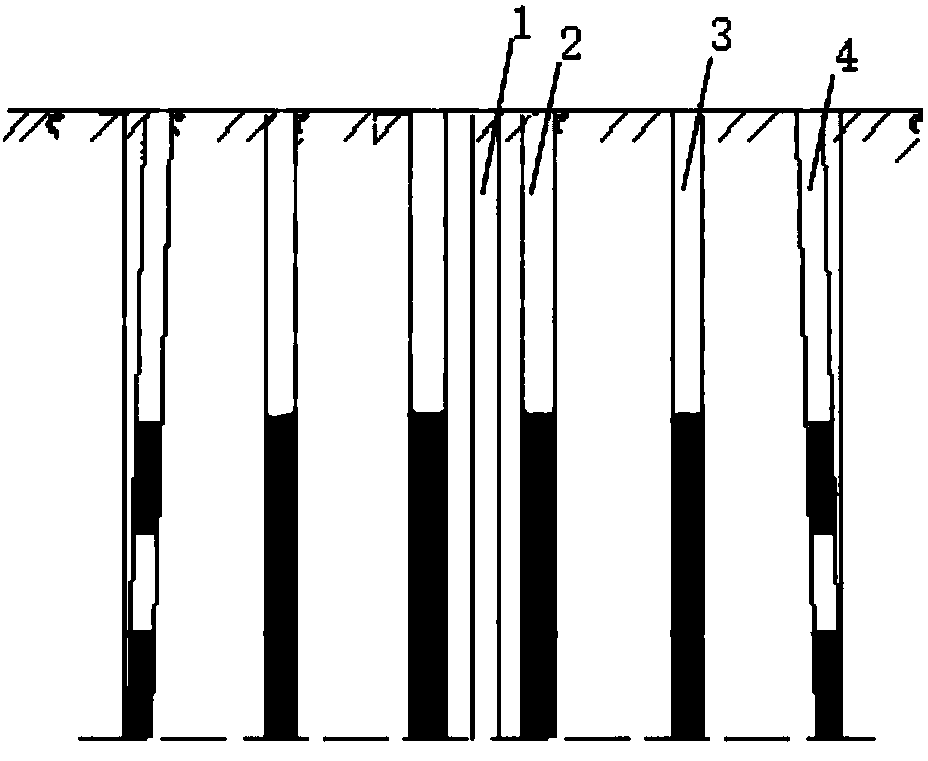

Image

  • Detonation method of bridge cylinder pile foundation with pile foundation diameter ranging from 1.4 m to 1.6 m
  • Detonation method of bridge cylinder pile foundation with pile foundation diameter ranging from 1.4 m to 1.6 m
  • Detonation method of bridge cylinder pile foundation with pile foundation diameter ranging from 1.4 m to 1.6 m

Examples


Embodiment 1

[0028] This embodiment provides a method for blasting a cylindrical pile foundation of a bridge with a pile foundation diameter of 1.5 m, comprising the following steps:

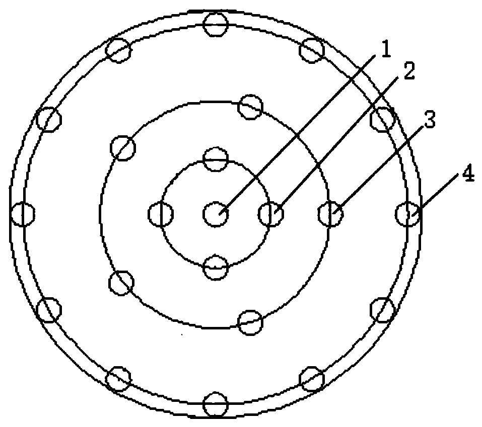
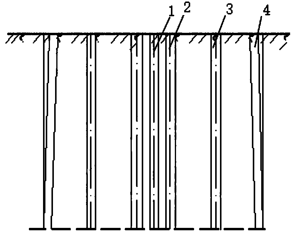
[0029] Drilling: such as figure 1 with figure 2 As shown, a central hollow hole 1 is vertically arranged along the centerline of the cylindrical pile foundation, and the inner ring of the blast hole is formed with the centerline of the cylindrical pile foundation as the center and with a radius of 0.15m. The middle circle of the blast hole is formed as a radius, and the outer ring of the blast hole is formed with the centerline of the cylindrical pile foundation as the center and the radius of 0.65m. There are four vertically arranged cut holes 2 evenly distributed on the inner ring of the blast hole. Five vertically arranged auxiliary holes 3 are evenly distributed on the middle ring of the blast hole, and 12 obliquely arranged peripheral holes 4 are evenly distributed on the outer ring of the blast hole;...

Embodiment 2

[0035] This embodiment provides a method for blasting a cylindrical pile foundation of a bridge with a pile foundation diameter of 1.6 m, comprising the following steps:

[0036] Drilling: such as figure 1 with figure 2 As shown, a central hole 1 is arranged vertically along the centerline of the cylindrical pile foundation, and the inner circle of the blast hole is formed with the centerline of the cylindrical pile foundation as the center and with a radius of 0.17m. The middle circle of the blast hole is formed as a radius, and the outer ring of the blast hole is formed with the center line of the cylindrical pile foundation as the center and the radius of 0.67m. Four vertically arranged cut holes 2 are evenly distributed on the inner ring of the blast hole. Five vertically arranged auxiliary holes 3 are evenly distributed on the middle ring of the blast hole, and 12 obliquely arranged peripheral holes 4 are evenly distributed on the outer ring of the blast hole; the centr...

Embodiment 3

[0042] This embodiment provides a method for blasting a cylindrical pile foundation of a bridge with a pile foundation diameter of 1.4 m, comprising the following steps:

[0043] Drilling: such as figure 1 with figure 2 As shown, a central hole 1 is arranged vertically along the centerline of the cylindrical pile foundation, and the inner circle of the blast hole is formed with the centerline of the cylindrical pile foundation as the center and with a radius of 0.13m. The middle circle of the blast hole is formed with a radius of 0.5 m, and the outer ring of the blast hole is formed with the center line of the cylindrical pile foundation as the center and the radius of 0.63 m. Four vertically arranged cut holes 2 are evenly distributed on the inner ring of the blast hole. Five vertically arranged auxiliary holes 3 are evenly distributed on the middle ring of the blast hole, and 12 obliquely arranged peripheral holes 4 are evenly distributed on the outer ring of the blast hol...


PUM


Abstract

The invention relates to a detonation method of a bridge cylinder pile foundation with the pile foundation diameter ranging from 1.4 m to 1.6 m. The detonation method comprises the steps of hole drilling, explosive charging, blasthole opening blocking and detonation. The hole drilling method is that a center empty hole is vertically formed along the center line of the cylinder pile foundation, thecenter line of the cylinder pile foundation is the center, a blasthole inner ring is formed with the radius being 0.13 m-0.17 m, a blasthole middle ring is formed with the radius being 0.33 m-0.37 m,a blasthole outer ring is formed with the radius being 0.63 m-0.67 m, four vertically-arranged grooving holes are evenly distributed on the blasthole inner ring, five vertcialy-arranged assisting holes are evenly formed in the blasthole middle ring, and twelve inclined perimeter holes are evenly distributed on the blasthole outer ring; included angles formed between the central axes of the perimeter holes and the vertical direction are arccot10-arccot12, and the distances between hole tops of the perimeter holes and the center empty hole are smaller than the distances between hole bottoms ofthe perimeter holes and the center empty hole. The detonation method is high in detonation quality, high in construction efficiency and low in detonation cost.

Description

technical field [0001] The invention relates to a blasting method for a bridge cylindrical pile foundation with a pile foundation diameter of 1.4-1.6m, belonging to the technical field of bridge construction. Background technique [0002] Cylindrical piles are widely used in bridge engineering. Cylindrical pile foundation excavation is usually constructed by blasting method, but the existing method has poor blasting quality, high blasting cost and low construction efficiency. The blasting shock wave, blasting seismic wave and flying rocks will damage the wall of the pile hole, and the wall will collapse, fall off, crack, etc., thereby destroying the effect of the wall of the pile hole and affecting the stability of the surrounding rock of the pile hole. Damage the construction facilities and equipment near the main access road above the excavation area. Therefore, it is necessary to choose a suitable blasting method when excavating and blasting cylindrical pile holes. On th...

Claims


Application Information

Patent Timeline
Patent Type & Authority Applications(China)
IPC IPC(8): F42D1/00
CPCF42D1/00
Inventor 周晨黄永亮邢海龙
Owner NO 2 ENG CO LTD OF CCCC FIRST HIGHWAY ENG
Learn More