

High-strength steel narrow gap welding process and material
A welding process, narrow gap technology, applied in welding/cutting medium/material, welding medium, welding equipment, etc., to achieve the effect of eliminating complicated processes
Inactive Publication Date: 2018-05-25
张宇
View PDF0 Cites 0 Cited by
- Summary
- Abstract
- Description
- Claims
- Application Information
AI Technical Summary
Problems solved by technology
[0005] In addition, due to the large difference in energy density and thermal cycle curve between laser welding and arc welding, the performance of the same welding material in the two welding methods is completely different.
Method used
View moreImage
Smart ImageViewing Examples

Examples
Embodiment 1-2
[0050] A solid core wire with a diameter of 1.6mm is used.
[0051] The root opening gap is 5mm.
[0052] The quality and performance of welded joints are shown in Table 3.
Embodiment 3-4
[0054] A solid core wire with a diameter of 1.4mm is used.
[0055] Root opening gap 4mm.
[0056] The quality and performance of welded joints are shown in Table 3.
Embodiment 5-6
[0058] A solid core wire with a diameter of 1.6mm is used.
[0059] The root opening gap is 3mm.
[0060] The quality and performance of welded joints are shown in Table 3.
Login to View More PUM
| Property | Measurement | Unit |
|---|---|---|
| Yield strength | aaaaa | aaaaa |
| Tensile strength | aaaaa | aaaaa |
| Impact energy | aaaaa | aaaaa |
Abstract
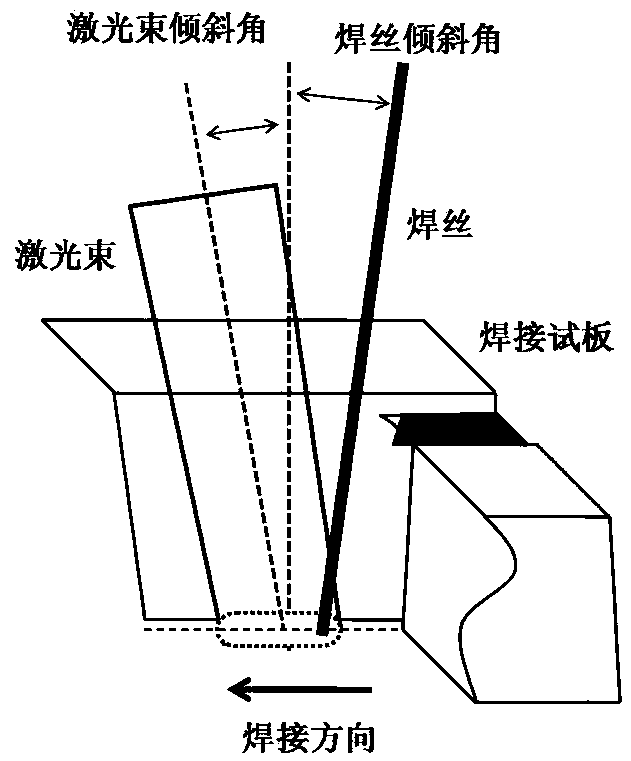
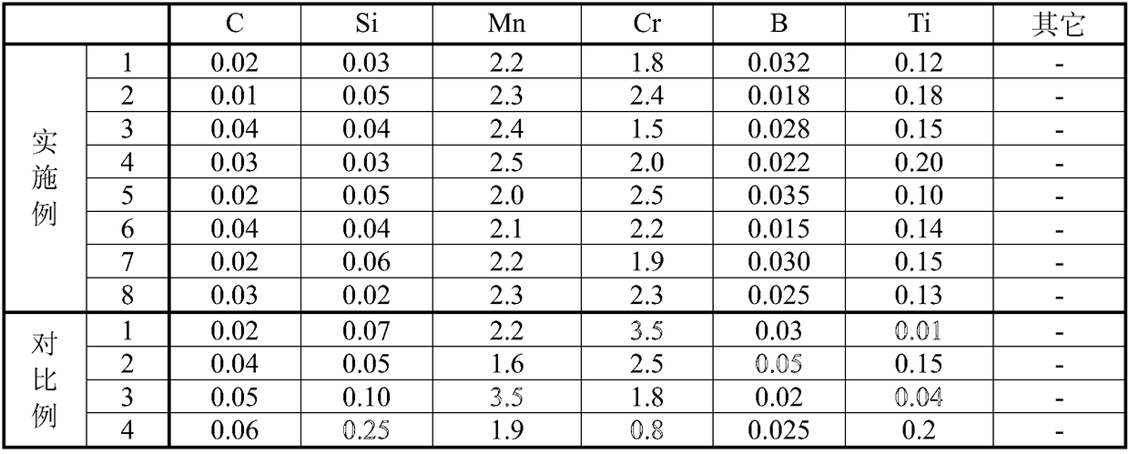
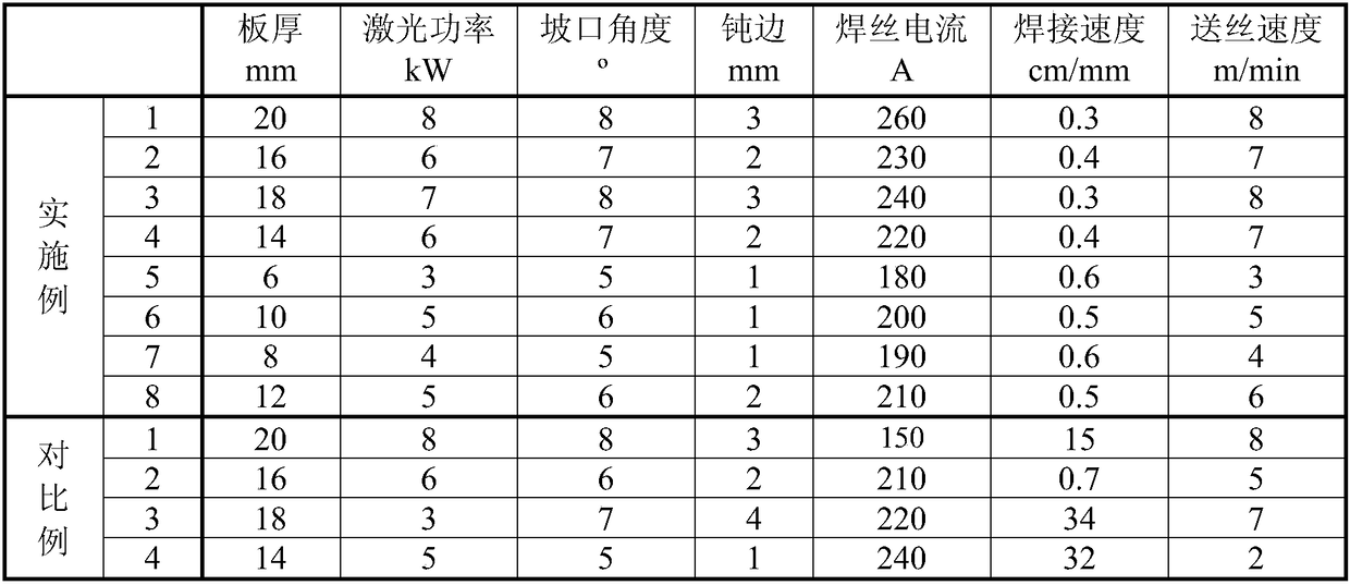
The invention relates to a high-strength steel narrow gap welding process. According to the process, a laser device with the power being 3-8kW is adopted, the dimensions of rectangular light spots arelarger than or equal to 20mm<2>, and the welding speed is 0.3-0.6m / min; the wire feeding speed is 3-8m / min, the electric current of a welding wire is 180-260A, and a U-shaped groove with the angle being 5-10 degrees is adopted; the welding wire includes 0-0.08% of C, 0-0.1% of Si, 1.5%-3.0% of Mn, 1.0%-3.0% of Cr, 0.05%-0.3% of Ti and 0.01%-0.05% of B; and single-pass through welding of a high-strength steel plate within the thickness being within the range of 20mm is conducted, cracks are avoided, and low-temperature toughness of -40 DEG C is 80J or above.
Description
technical field [0001] The invention relates to a narrow-gap welding process and material for high-strength steel, belonging to the field of welding technology, in particular to a laser welding process and welding wire for 800MPa high-strength steel. Background technique [0002] In recent years, high-strength steel with a tensile strength of 800MPa has been used in large-scale structures such as construction machinery, pressure water pipes, and offshore platforms to improve the bearing capacity and comprehensive performance of structural components. [0003] Welding such steel plates by ordinary arc welding often leads to softening of the weld, and the welding efficiency is not high. In order to improve the negative impact of large heat input caused by arc welding and other methods, recently, laser welding, laser-arc hybrid welding and other methods have begun to be used in the welding of 800MPa high-strength steel. Due to the characteristics of high energy and concentrati...
Claims
Login to View More Application Information
Patent Timeline
 IPC IPC(8): B23K26/348B23K26/12B23K26/24B23K35/30B23K103/04
CPCB23K26/24B23K26/123B23K26/348B23K35/3073B23K35/308
Inventor张宇
Owner张宇