Narrow gap laser-electric arc hybrid welding gas shielding device and adjusting method

A gas protection device and composite welding technology, applied in laser welding equipment, welding equipment, metal processing equipment, etc., can solve the problems of melting, damage, and limited adjustable height, etc., to ensure laminar flow effect, good protection, reduce The effect of welding consumables consumption

Active Publication Date: 2018-05-25
HUAZHONG UNIV OF SCI & TECH
View PDF7 Cites 3 Cited by
  • Summary
  • Abstract
  • Description
  • Claims
  • Application Information

AI Technical Summary

Problems solved by technology

The device is an external nozzle mechanism, which does not extend into the groove. The distance between the lower end of the nozzle and the upper surface of the workpiece is 1-5mm, and the adjustable height is limited.
Secondly, the telescopic part of the nozzle is a cylindrical cylinder, which is not suitable for narrow gap laser-arc hybrid welding, otherwise the end of the cylindrical nozzle close to the surface of the workpiece will be burned and damaged by the laser

Method used


Image

  • Narrow gap laser-electric arc hybrid welding gas shielding device and adjusting method
  • Narrow gap laser-electric arc hybrid welding gas shielding device and adjusting method
  • Narrow gap laser-electric arc hybrid welding gas shielding device and adjusting method

Examples


Embodiment 1

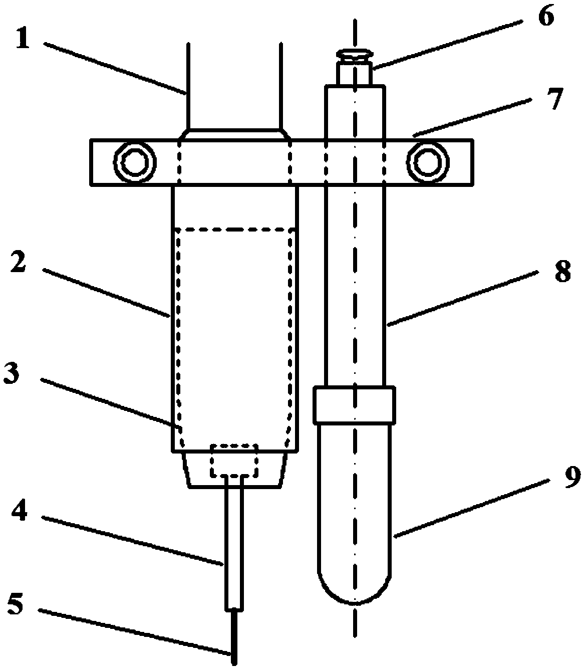
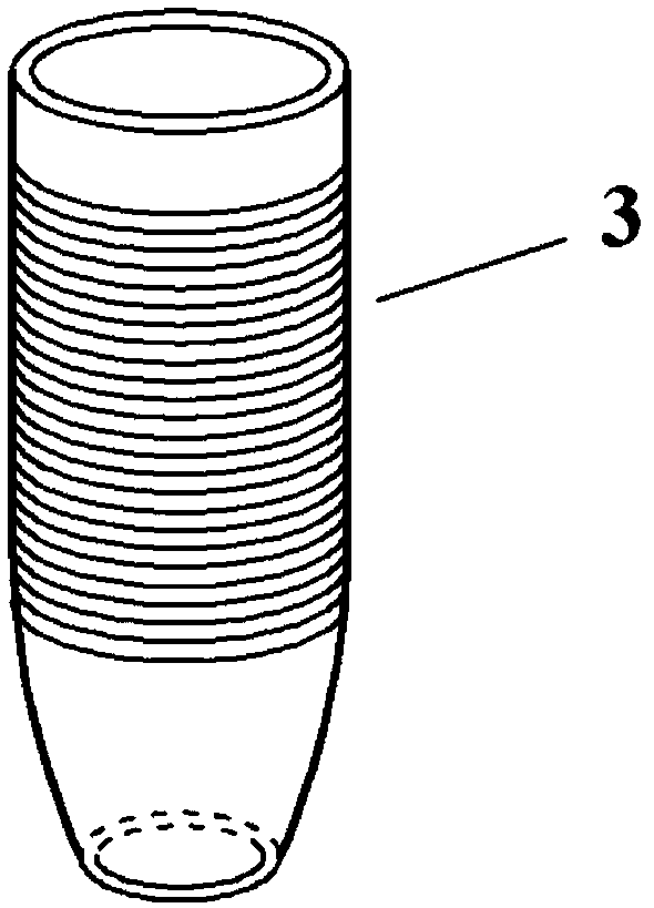
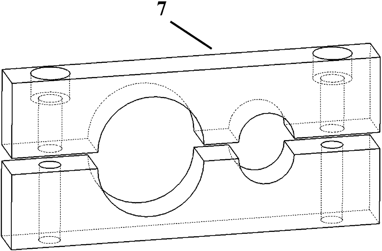
[0039] When the distance between the bottom of the groove or the surface of the weld and the upper surface of the workpiece 11 is t>30mm, it is suitable for Figure 5 situation shown. Install the rear auxiliary air flat nozzle assembly, including the quick insertion of the air guide tube 6, the clamping block 7, the auxiliary air connecting rod 8 and the rear auxiliary air flat nozzle 9. A separate protective gas inlet tube is used to connect the quick insertion of the airway tube 6. Rotate the main nozzle inner cylinder 3 (the main nozzle outer cylinder 2 does not shift), and at the same time move the auxiliary gas connecting rod 8 equipped with the rear auxiliary gas flat nozzle 9 along the direction parallel to the end of the welding wire 5, and the main nozzle assembly and the rear Set the auxiliary air flat nozzle assembly for coarse adjustment respectively. Adjust the welding torch 1 to the welding height along the z-axis direction, finely adjust the main nozzle inner ...

Embodiment 2

[0042] When the distance between the bottom of the groove or the surface of the weld and the upper surface of the workpiece 11 is t Image 6 situation shown. At this time, the main nozzle assembly is fully capable of protecting the molten pool and cooling the welding wire. In order to avoid the risk of the rear auxiliary air flat nozzle 9 colliding with the side wall of the groove due to misoperation and to speed up the welding preparation work, the rear auxiliary nozzle 9 is removed. The air flat nozzle assembly includes the quick insertion of the air guide tube 6, the clamping block 7, the auxiliary air connecting rod 8 and the rear auxiliary air flat nozzle 9. Rotate the inner cylinder 3 of the main nozzle (the outer cylinder 2 of the main nozzle does not move), and make rough adjustments to the main nozzle assembly. Adjust the welding torch 1 to the welding height along the z-axis, and finely adjust the inner tube 3 of the main nozzle so that it is 2-5mm higher than the upp...

Embodiment 3

[0045] When the distance from the bottom of the groove or the surface of the weld to the upper surface of the workpiece 11 is t=0, it is suitable for Figure 7 situation shown. Continue to rotate the inner cylinder 3 of the main nozzle (the outer cylinder 2 of the main nozzle does not shift), and make rough adjustments to the main nozzle assembly. Adjust the welding torch 1 to the welding height along the z-axis, and finely adjust the inner tube 3 of the main nozzle so that it is 2-5mm higher than the upper surface of the workpiece 11 .

[0046] When the distance between the bottom of the groove or the surface of the weld seam and the upper surface of the workpiece is t=0, the method described in this embodiment is used for welding. Since the protective gas blowing method of the main nozzle assembly is the same as that of the traditional fixed-length nozzle, the weld seam The shape is good, the surface of the weld is uniform, continuous, smooth and concave, and defects such a...


PUM


Abstract

The invention discloses a narrow gap laser-electric arc hybrid welding gas shielding device and an adjusting method. The device comprises a main spraying nozzle assembly and a back-mounted auxiliary gas flat spraying nozzle assembly; the main spraying nozzle assembly comprises a main spraying nozzle outer barrel and a main spraying nozzle inner barrel, the main spraying nozzle outer barrel is of abullet-shaped spraying nozzle structure, and the front end is provided with a conic shape with a smooth convergence curve; and the back-mounted auxiliary gas flat spraying nozzle assembly comprises agas guide pipe quick insertion, a clamping block, an auxiliary gas connecting rod and a back-mounted auxiliary gas flat spraying nozzle. In the adjustment process, the main spraying nozzle inner barrel can move up and down in the welding gun axis direction, the back-mounted auxiliary gas flat spraying nozzle assembly can be adjusted to move up and down in the direction parallel to the welding gunaxis direction by releasing the clamping block, and stretchable adjustment of the distance between the main spraying nozzle and the workpiece surface and the distance between the back-mounted auxiliary gas flat spraying nozzle and the notch bottom is finally achieved in the multi-layer welding process. The narrow gap laser-electric arc hybrid welding gas shielding device is compact in structure,convenient to adjust and high in reliability, the hybrid welding adjusting efficiency can be obviously improved, and high-quality welding of large-thickness materials is achieved.

Description

technical field [0001] The invention belongs to the field of welding technology, and relates to a narrow-gap laser-arc composite welding gas blowing device, and more particularly relates to a gas protection device and an adjustment method for narrow-gap laser-arc composite welding. Background technique [0002] Narrow gap welding usually refers to the method of placing a steel plate with a thickness of more than 30mm and opening a groove relative to a gap smaller than the thickness of the plate, and then performing mechanized or automatic arc welding (when the plate thickness is less than 200mm, the gap is less than 20mm; when the plate thickness exceeds 200mm , the gap is less than 30mm). The gap used in the existing simple arc welding narrow gap welding is mostly 8-20mm, or even wider, and the welding speed is usually 0.2-0.3m / min. Although this narrow-gap welding technology has simple equipment and low cost, it needs to be further improved in terms of welding deformation...

Claims


Application Information

Patent Timeline
Patent Type & Authority Applications(China)
IPC IPC(8): B23K26/348B23K26/70B23K26/346B23K28/02
CPCB23K26/346B23K26/348B23K26/70B23K28/02
Inventor 高明孟云飞李耿曾晓雁
Owner HUAZHONG UNIV OF SCI & TECH
Why Eureka
Try Eureka