Back plate for photovoltaic module and solar battery containing back plate

A technology of solar cells and photovoltaic modules, applied in the field of solar cells, to achieve the effects of reducing the probability of occurrence, delaying discoloration, and improving water resistance

Inactive Publication Date: 2018-05-25
CSI SOLAR POWER GROUP CO LTD +1
View PDF3 Cites 0 Cited by
  • Summary
  • Abstract
  • Description
  • Claims
  • Application Information

AI Technical Summary

Problems solved by technology

[0008] How to develop a low-water-permeable backplane to prevent external water vapor from entering the module through the backplane, causing the phenomenon of "snail pattern", is a technical problem that needs to be solved in this field

Method used


Image

  • Back plate for photovoltaic module and solar battery containing back plate
  • Back plate for photovoltaic module and solar battery containing back plate
  • Back plate for photovoltaic module and solar battery containing back plate

Examples


Embodiment 1

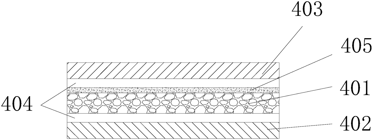
[0039] A backsheet for a photovoltaic module, comprising a PET layer 401 with a thickness of 250 μm; an inorganic water-blocking layer (silicon dioxide layer) 405 with a thickness of 15 μm deposited on the side of the PET layer 401 close to the air, through a 10 μm thick The glue layer 404 is bonded to the outer contact layer (PVDF fluorine layer) 403 with a thickness of 20 μm on the side of the inorganic water blocking layer 405, and is bonded to the side of the PET layer 401 away from the air through the glue layer 404 with a thickness of 10 μm. The encapsulant film contacts the inner contact layer 402 with a thickness of 50 μm.

Embodiment 2

[0047] The difference from Example 1 is that the inorganic water blocking layer is a silicon nitride layer with the same thickness (15 μm).

Embodiment 3

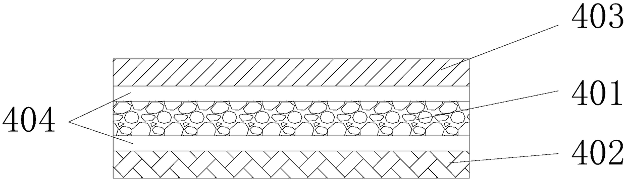
[0049] A backsheet for a photovoltaic module, comprising a PET layer 401 with a thickness of 220 μm; an inorganic water-blocking layer (silicon nitride layer) 405 with a thickness of 10 μm deposited on the side of the PET layer 401 close to the air; The glue layer 404 is bonded to the outer contact layer (PVDF fluorine layer) 403 with a thickness of 18 μm on the side of the inorganic water blocking layer 405, and is bonded to the side of the PET layer 401 away from the air through the glue layer 404 with a thickness of 8 μm. The encapsulant film contacts the inner contact layer 402 with a thickness of 50 μm.


PUM

PropertyMeasurementUnit
thicknessaaaaaaaaaa
thicknessaaaaaaaaaa
thicknessaaaaaaaaaa

Abstract

The invention relates to a back plate for a photovoltaic module. The back plate for the photovoltaic module is characterized by comprising a PET layer, an inorganic water blocking layer and an external contact layer, wherein the inorganic water blocking layer is deposited on one side, close to air, of the PET layer; the external contact layer is bonded at one side of the water blocking layer. According to the back plate disclosed by the invention, the inorganic water blocking layer is arranged between the PET layer and the external contact layer, so that the water blocking property of the backplate is improved, the permeability rate of the back plate is reduced and reaches 1.0g / m<2>.d or less (the temperature is 38 DEG C, relative humidity is 90 percent, RH and an infrared test is adopted), the infiltration of water into the edge of the battery and microcracks are reduced, color change of a battery piece grid line can be retarded, and the occurrence probability of snail tracks of thephotovoltaic module can be reduced; besides, compared with a back plate with a KPE structure in the prior art, the back plate for the photovoltaic module, provided by the invention, has the advantagesthat the influence on production process is avoided and the back plate can be prepared by using an existing preparation progress of the back plate.

Description

technical field [0001] The invention belongs to the technical field of solar cell preparation, and in particular relates to a back plate for a photovoltaic module and a solar cell comprising the same. Background technique [0002] Therefore, in today's environment where energy problems are becoming more and more prominent, solar energy, as a renewable energy source, has always been a new energy source that countries have focused on research. Solar cells use the photovoltaic effect to convert solar energy into electrical energy, and are gradually being widely used. The demand for them is expanding day by day, and the market prospect is very promising. [0003] The structure of the solar cell module in the prior art includes: a cell 100, an encapsulation film 200 (usually EVA) wrapping the cell, a transparent cover 300 arranged on the side of the encapsulation film close to sunlight, and The backplane 400 on the side where the encapsulation film is away from sunlight, such as...

Claims


Application Information

Patent Timeline
Patent Type & Authority Applications(China)
IPC IPC(8): B32B27/06B32B27/08B32B27/36B32B7/12B32B27/30H01L31/048H01L31/049
CPCY02E10/50B32B27/08B32B7/12B32B27/304B32B27/36B32B2255/10B32B2255/20B32B2307/73B32B2457/12H01L31/0481H01L31/049
Inventor 赵圣云杨连丽许涛
Owner CSI SOLAR POWER GROUP CO LTD
Why Eureka
Try Eureka