Cooling system for marine diesel engine

A diesel engine and cooling system technology, which is applied to the cooling of the engine, engine components, machines/engines, etc., can solve the problems of large fresh water consumption, short service life, and easy corrosion of the inner cavity of the diesel engine, so as to save fresh water consumption and solve the problem of fresh water consumption of large effects

Pending Publication Date: 2018-05-25
山东华源莱动内燃机有限公司
View PDF0 Cites 0 Cited by
  • Summary
  • Abstract
  • Description
  • Claims
  • Application Information

AI Technical Summary

Problems solved by technology

[0004] The purpose of the present invention is to provide a new cooling system suitable for marine diesel engines to solve the technical problems that the existing marine diesel engines consume a lot of fresh water, and the inner cavity of diesel engines that use seawater instead of fresh water is easy to rust and has a short service life.

Method used


Image

  • Cooling system for marine diesel engine
  • Cooling system for marine diesel engine

Examples


Embodiment 1

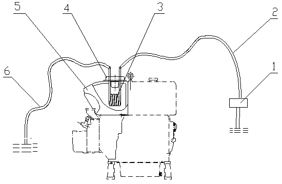
[0015] Embodiment 1: as figure 1 As shown, a marine diesel engine cooling system is applied to ships operating at sea, including a cooling water tank, a water-saving funnel, and a heat exchanger. And the water outlet, the water inlet end and the water outlet end pass through the water-saving funnel upwards, so that the heat exchanger is relatively fixed in the cooling fresh water inside the cooling water tank; the water inlet of the heat exchanger is connected to the seawater inlet pipe, and its water outlet is connected to the seawater outlet pipe.

[0016] When the diesel engine is working, the structure and principle that the diesel engine uses the fresh water in the cooling water tank to cool the diesel engine remain unchanged. The cooling fresh water temperature will increase with time. In this embodiment, the seawater at normal temperature is driven by the propeller blades outside the hull, enters the heat exchanger through the seawater inlet pipe, exchanges heat with t...

Embodiment 2

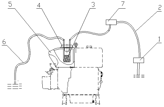
[0017] Embodiment 2: as figure 2 As shown, a marine diesel engine cooling system is applied to ships operating at sea. Its structure and working method are basically the same as those in Example 1, the difference is that a seawater storage system is connected between the heat exchanger water inlet and the seawater inlet pipe. Container, the seawater water storage container is arranged on the position higher than the diesel engine water tank on board. When the diesel engine is working, the propeller blades of the marine engine are used to drive the seawater at normal temperature to enter the heat exchanger through the seawater inlet pipe and the seawater storage container.

Embodiment 3

[0018] Embodiment 3: as Figure 1-2 As shown, a marine diesel engine cooling system is applied to ships operating at sea. Its structure and working method are basically the same as those in Embodiment 1, except that the heat exchanger is made of copper tubes. Its implementation effect is basically consistent with embodiment 1.


PUM


Abstract

The invention relates to a cooling system for a marine diesel engine. The cooling system comprises a cooling water tank, a water-saving funnel and a heat exchanger; the water-saving funnel are fixedlyinstalled at the top part of the cooling water tank; two ends of the heat exchanger are provided with a water inlet and a water outlet respectively, wherein the water inlet end and the water outlet end penetrate through the water-saving funnel upwards, so that the heat exchanger is fixedly positioned in cooling fresh water inside the cooling water tank; and the water inlet of the heat exchanger is connected with a seawater inlet pipe, and the water outlet is connected with a seawater outlet pipe. According to the cooling system, the heat exchanger is arranged in the cooling water tank of thediesel engine, rich seawater resources in offshore operation of ships are further utilized, so that the fresh water for the cooling system of the diesel engine is cooled, and therefore the problem that consumption of the fresh water for the marine diesel engine is large is solved; and meanwhile, the problems that an inner cavity of the diesel engine is easy to rust and is short in service life dueto the fact that seawater is directly used for replacing fresh water to enter the cooling system of the diesel engine are solved.

Description

technical field [0001] The invention belongs to the technical field of engine cooling systems, and in particular relates to a cooling system for marine diesel engines. Background technique [0002] The function of the diesel engine cooling system is to dissipate part of the heat of the strongly heated parts in time when the diesel engine is working, so as to ensure that the diesel engine works at the most suitable temperature state. [0003] At present, ships operating at sea generally use water-cooled diesel engines as power. When the diesel engine is working, the fresh water in the cooling water tank circulates continuously in the diesel engine cooling system to cool the diesel engine. With the extension of working hours, the temperature of the cooling fresh water in the water tank rising and even evaporating. Therefore, the conventional water-cooled diesel engine consumes a lot of fresh water and needs to be supplemented with fresh water from time to time. Due to the pa...

Claims


Application Information

Patent Timeline
Patent Type & Authority Applications(China)
IPC IPC(8): F01P3/20
CPCF01P3/207F01P2050/06F01P2070/52
Inventor 温象龙张天文刘同会李尧文李钢胡建立
Owner 山东华源莱动内燃机有限公司
Why Eureka
Try Eureka