
Optical proximity effect correction method and system

A technology of optical proximity effect and correction method, which is applied in the direction of optics, optomechanical equipment, microlithography exposure equipment, etc., can solve the problems of unable to effectively balance the correction results, product yield rate, and inability to adapt to accurate correction, etc., to achieve reduction Effects of deformation and deviation, improvement of yield rate, and precise correction

Active Publication Date: 2020-04-03
CSMC TECH FAB2 CO LTD
View PDF4 Cites 0 Cited by
  • Summary
  • Abstract
  • Description
  • Claims
  • Application Information

AI Technical Summary

Problems solved by technology

However, such a method cannot effectively balance the correction results, and thus cannot adapt to accurate corrections in complex graphics environments.
Products corrected by this OPC correction method will still have yield problems

Method used


Image

  • Optical proximity effect correction method and system
  • Optical proximity effect correction method and system
  • Optical proximity effect correction method and system

Examples


Embodiment Construction

[0023] A preferred embodiment of the invention is given in . However, the present invention can be embodied in many different forms and is not limited to the embodiments described herein. Rather, these embodiments are provided so that the disclosure of the present invention will be thorough and complete.

[0024] Unless otherwise defined, all technical and scientific terms used herein have the same meaning as commonly understood by one of ordinary skill in the technical field of the invention. The terms used herein in the description of the present invention are for the purpose of describing specific embodiments only, and are not intended to limit the present invention. As used herein, the term "and / or" includes any and all combinations of one or more of the associated listed items.

[0025] The idea of ​​the present invention is to improve the traditional OPC correction method, introduce the concept of weight to different target points on the graph, and target the target po...


PUM


Abstract

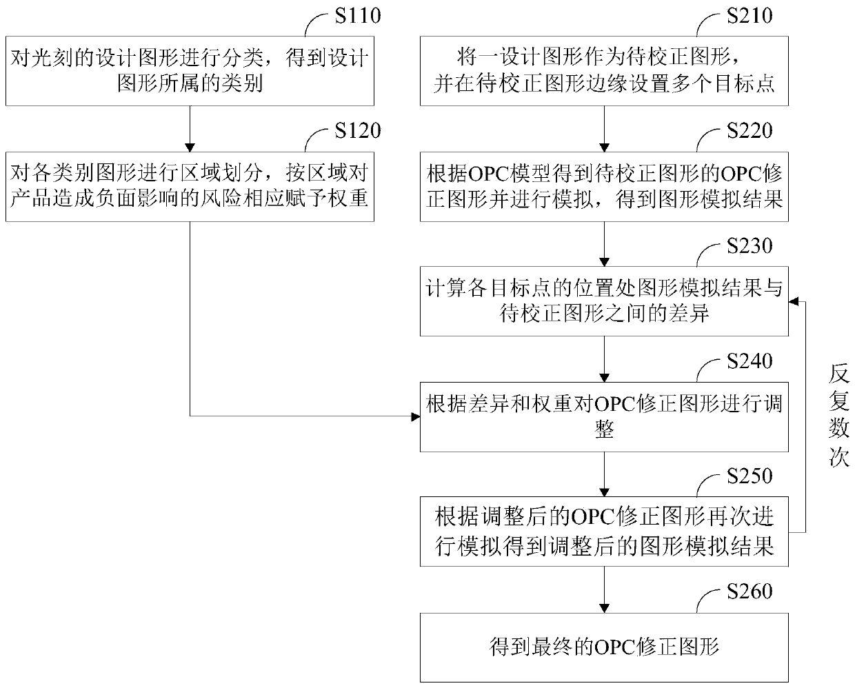
The invention relates to an optical proximity effect correction method and system. The method comprises the following steps: categorizing photoetching design patterns; conducting regional division oneach class of patterns, assigning weights to risks causing negative effects to products according to regions; using design patterns as to-be-corrected design patterns and setting multiple target points at the edges of the pattern; obtaining OPC correction patterns of the to-be-corrected design patterns based on an OPC model and performing simulations to obtain pattern simulation results; calculating differences between the pattern simulation results and the to-be-corrected patterns at the positions of each target point; adjusting the OPC correction patterns according to the differences and theweights, and conducting simulation again to obtain adjusted pattern simulation results; repeatedly performing the two steps to obtain the final OPC correction patterns. The optical proximity effect correction method introduces a concept of weights to different target points on the patterns. When correction requirements of different regions conflict, priority is given to the correction requirements of the high-weight target points, so that yield rate of components can be improved.

Description

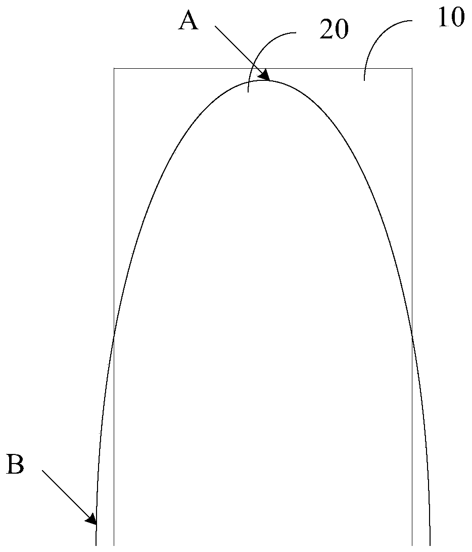
technical field [0001] The invention relates to an optical proximity correction (OPC) process, in particular to an optical proximity correction method and an optical proximity correction system. Background technique [0002] The critical dimensions (CD) of the active region level (TO), gate oxide layer (GT) and metal wiring level (An) are getting smaller and smaller at the key levels of the technology node of 0.18 microns and below, and the CD is close to or even Smaller than the wavelength of light used in photolithography. Therefore, in the photolithography process, due to light interference and diffraction phenomena, there are certain deformations and deviations between the photolithography pattern actually obtained on the silicon wafer and the mask pattern. This error in lithography directly affects component performance and production yield. In order to eliminate this error as much as possible, an effective method is to use optical proximity correction (OPC) process. ...

Claims


Application Information

Patent Timeline
Patent Type & Authority Patents(China)
IPC IPC(8): G03F7/20
CPCG03F7/70441
Inventor 万金垠王谨恒张雷陈洁
Owner CSMC TECH FAB2 CO LTD
Learn More