Manufacturing method of resistor, manufacturing method of chip resistor and chip resistor

A manufacturing method and technology of a resistor body, which are applied in the direction of manufacturing resistors, resistor manufacturing, and resistors by photolithography, can solve the problem of difficulty in ensuring the target resistance value, etc., and achieve the effect of improving the resistance power and pulse surge performance.

Active Publication Date: 2018-05-25
GUANGDONG FENGHUA ADVANCED TECH HLDG
View PDF5 Cites 4 Cited by
  • Summary
  • Abstract
  • Description
  • Claims
  • Application Information

AI Technical Summary

Problems solved by technology

Among them, the resist paste used for printing resistors contains solvents, which will volatilize after drying and sintering, and the influence of printing flatness, which finally leads to the resistance value after sintering can only be within a certain range, and it is difficult to ensure that it can be directly achieved. The target resistance value, in order to improve the qualified rate, needs to be repaired to achieve it; usually, laser trimming is used to repair the resistor body at the cost of breaking down the internal structure of the resistor body to ensure that the target resistance value is reached, see figure 2 , there are cutting grooves in the internal structure of the resistor body after repairing resistance; among them, figure 2 Part (A) marks the width dimension a of the repair resistor, and the change of the width dimension a of the resistor repair is generally within 1 / 2 of the width of the resistor body; the circle marks the obvious weakness of the power of the resistor body and the anti-pulse surge performance deficiencies, figure 2 Part (B) is a schematic diagram of the current flowing through the resistor body. The current overload position is concentrated on the resistor body at the repair point, so the power and anti-pulse surge performance of the resistor body are limited. figure 2 Weaknesses shown in (A)

Method used


Image

  • Manufacturing method of resistor, manufacturing method of chip resistor and chip resistor
  • Manufacturing method of resistor, manufacturing method of chip resistor and chip resistor
  • Manufacturing method of resistor, manufacturing method of chip resistor and chip resistor

Examples


Embodiment Construction

[0042] The following will clearly and completely describe the technical solutions in the embodiments of the present invention with reference to the accompanying drawings in the embodiments of the present invention. Obviously, the described embodiments are only some, not all, embodiments of the present invention. Based on the embodiments of the present invention, all other embodiments obtained by persons of ordinary skill in the art without creative efforts fall within the protection scope of the present invention.

[0043] see image 3 , an embodiment of the present invention provides a method for manufacturing a resistor, image 3 It is a schematic flow chart of this embodiment, including:

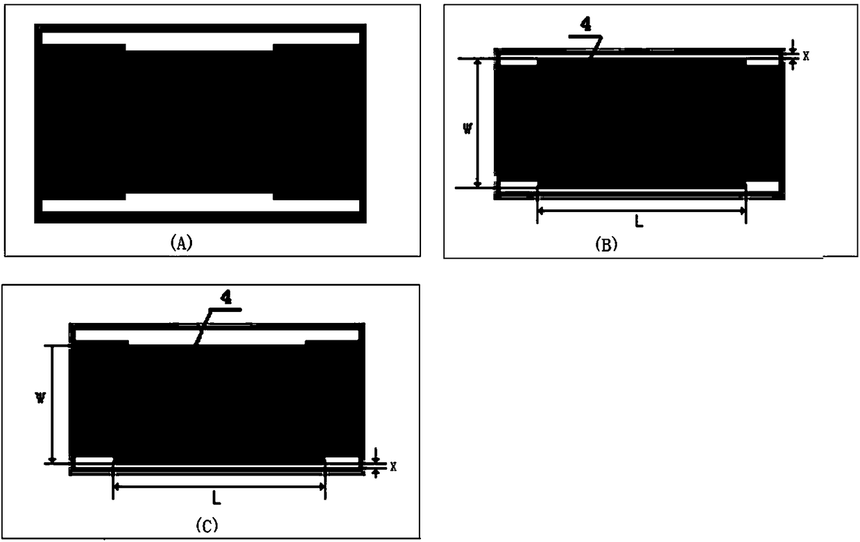
[0044] S1. Obtain the first printed design size of the target resistor, and increase the cross-sectional area of ​​the first printed design size according to a preset ratio value to obtain the second printed design size; wherein, the first printed design size is based on the target resis...


PUM


Abstract

The invention discloses a manufacturing method of a resistor. The manufacturing method comprises the following steps: obtaining a first printing design size of a target resistor, and increasing the cross section area of the first printing design size according to a preset ratio, so as to obtain a second printing design size, wherein the first printing design size is designed according to the target resistance of the target resistor; according to the second printing design size, printing the resistor, so as to obtain a printed resistor; reducing the cross section area of the printed resistor bya resistance modifying technology, so as to enable the printed resistor to reach the target resistance, thereby obtaining the final resistor. The manufacturing method provided by the invention has the advantage that the power and pulse surge properties of the resistor are greatly improved.

Description

technical field [0001] The invention relates to the field of electronic components, in particular to a method for manufacturing a resistor, a method for manufacturing a chip resistor and the chip resistor. Background technique [0002] see figure 1 , Chip resistors are generally composed of ceramic substrate 1, back electrode 2, front electrode 3, resistor body 4, inner layer protection (primary protection layer) 5, outer layer protection (secondary protection layer) 6, terminal electrode 7, middle electrode 8 and external electrode 9. [0003] The manufacturing process of chip resistors mainly includes: screen production, printed back electrode, printed front electrode, printed resistor body, printed primary protection, laser trimming, printed secondary protection, primary division, terminal production, secondary division and electroplating these processes. Among them, the resist paste used for printing resistors contains solvents, which will volatilize after drying and ...

Claims


Application Information

Patent Timeline
Patent Type & Authority Applications(China)
IPC IPC(8): H01C13/00H01C17/00H01C17/06
CPCH01C13/00H01C17/003H01C17/06
Inventor 卢振强张俊李军郝聪敏练洁兰
Owner GUANGDONG FENGHUA ADVANCED TECH HLDG
Why Eureka
Try Eureka