Adjustable strain clamp

A tension clamp, adjustable technology, applied in the direction of adjusting/maintaining mechanical tension, etc., can solve the problem of reducing the service life of tension clamp and jumper, difficult to ensure the uniformity of jumper production process, and drainage of tension clamp. The problem of splint deformation and other problems can avoid the phenomenon of tip discharge, the structure is simple, and the cost of raw materials can be reduced.

Pending Publication Date: 2018-05-25
JIANGSU TIANNAN ELECTRIC POWER EQUIP
View PDF0 Cites 3 Cited by
  • Summary
  • Abstract
  • Description
  • Claims
  • Application Information

AI Technical Summary

Problems solved by technology

In the construction of transmission lines, the construction of tension clamps is difficult and requires high technical requirements. The existing tension clamps have shortcomings: first, it is difficult to accurately control the deviation between the drainage splint and the drainage clamp on the tension clamp. Therefore, it is difficult to ensure the uniformity of the jumper production process; the second is that the connection between the existing drainage splint and the aluminum tube adopts the form of welding, and the drainage splint has a certain gap relative to the aluminum tube. The technology of the welding personnel puts forward very high requirements, which increases the production cost and affects the electrical conductivity after a period of use; the third is to rely mainly on the experience of the construction personnel for visual judgment when crimping the tension clamp, and add auxiliary fixtures to ensure The deflection angle of the drainage splint is affected by the torsion of the wire itself during actual crimping. After the actual installation, the deflection angle of the drainage splint is quite different from the designed deflection angle. The drainage splint is deformed, so there is a safety hazard in the tension clamp during use, and it affects the appearance of the jumper, making it difficult for the entire construction to meet the requirements of design and safe operation, greatly reducing the service life of the tension clamp and the jumper. Therefore, it is necessary to improve the structure of the existing strain clamp to meet the actual circuit design requirements

Method used


Image

  • Adjustable strain clamp
  • Adjustable strain clamp
  • Adjustable strain clamp

Examples


Embodiment Construction

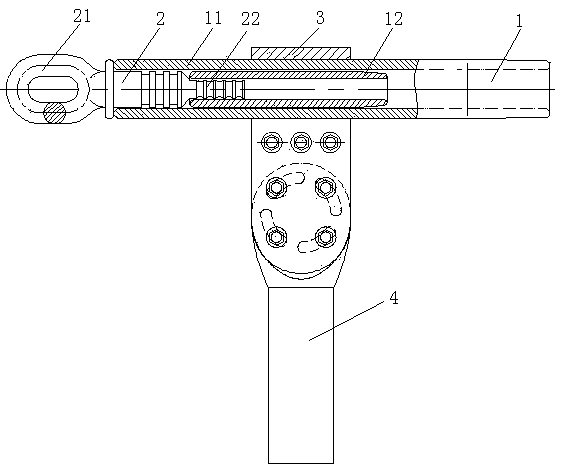
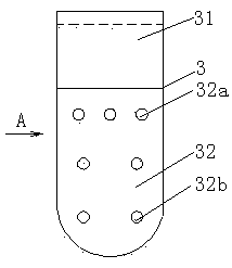
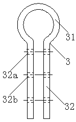
[0018] Refer to attached figure 1 , attached figure 2 , attached image 3 , attached Figure 4 , attached Figure 5 , an adjustable strain-resistant clamp of the present invention, which is composed of a clamp body 1, a steel anchor 2, a drainage splint 3, and a drainage clamp 4. The steel anchor 2 is inserted in the clamp body 1; the drainage splint 3 and The clamp body 1 is connected; one end of the drainage clamp 4 is connected to the drainage splint 3, and the other end is crimped with the jumper; the drainage splint 3 is in the form of a clamp and is set on the aluminum tube 11; The angle between the vertical position of the drainage splint and the drainage clamp is 0°, and the angle adjustment range of the drainage clamp relative to the drainage splint is -5°~45°; Set in the aluminum tube 11; the aluminum tube 11 and the crimping tube 12 are aluminum alloy hollow tubes; the inner diameter of the aluminum tube 11 is the same as the outer diameter of the wire; the out...


PUM


Abstract

The invention relates to an adjustable strain clamp which is composed of a clamp body, a steel anchor, a flow guide clamping plate and a flow guide clamp. Due to the fact that the flow guide clampingplate is installed on an aluminum pipe in a sleeving mode, can rotate around the aluminum pipe and are fixed after the declination angle of the aluminum pipe and the flow guide clamping plate is adjusted according to the design requirement, a dedicated angle positioning tool does not need to be adopted when the aluminum pipe is connected with a wire in a pressed mode; due to the fact that waist-shaped arc holes are formed in a connecting disc of the flow guide clamp, the angle that the flow guide clamp is relative to the flow guide clamping plate can be adjusted; due to the fact that the flowguide clamp is clamped by two flow guide clamp connection clamping plates when the flow guide clamping plate is connected with the flow guide clamp, the contact resistance is effectively reduced, andheat of the flow guide clamping plate is reduced; and due to the fact that a structure form of a shaft shoulder is arranged between a pull ring and an anchor rod of the steel anchor, the steel anchorcan be conveniently positioned in the aluminum pipe, and the phenomenon that rainwater enters the aluminum pipe from the end of the aluminum pipe is effectively prevented.

Description

technical field [0001] The invention relates to a strain clamp for transmission lines in the electric power industry, in particular to an adjustable strain clamp. Background technique [0002] After retrieving relevant patent documents, no adjustable tension clamp with the same structure as the present invention has been found. In the construction of transmission lines, the construction of tension clamps is difficult and requires high technical requirements. The existing tension clamps have shortcomings: first, it is difficult to accurately control the deviation between the drainage splint and the drainage clamp on the tension clamp. Therefore, it is difficult to ensure the uniformity of the jumper production process; the second is that the existing drainage splint and the aluminum tube are connected in the form of welding, and the drainage splint has a certain gap relative to the aluminum tube. The technology of the welding personnel puts forward very high requirements, wh...

Claims


Application Information

Patent Timeline
Patent Type & Authority Applications(China)
IPC IPC(8): H02G7/02
CPCH02G7/02
Inventor 姚建生朱小强
Owner JIANGSU TIANNAN ELECTRIC POWER EQUIP
Why Eureka
Try Eureka