Surge protection circuit having feedback control function

A surge protection and feedback circuit technology, applied in emergency protection circuit devices, emergency protection circuit devices for limiting overcurrent/overvoltage, circuit devices, etc., can solve problems such as inability to adequately handle surge events

Active Publication Date: 2018-05-25
NXP BV
View PDF10 Cites 4 Cited by
  • Summary
  • Abstract
  • Description
  • Claims
  • Application Information

AI Technical Summary

Problems solved by technology

[0004] However, ESD protection device 14 is only effective for a very short time (hundreds of nanoseconds or less), which may be much smaller than the time period of a

Method used


Image

  • Surge protection circuit having feedback control function
  • Surge protection circuit having feedback control function
  • Surge protection circuit having feedback control function

Examples


Example Embodiment

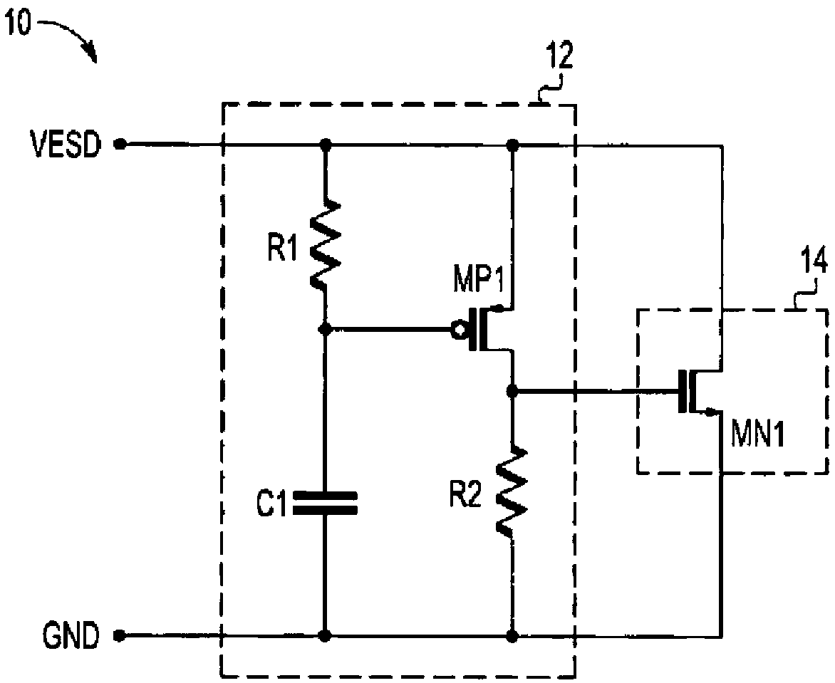
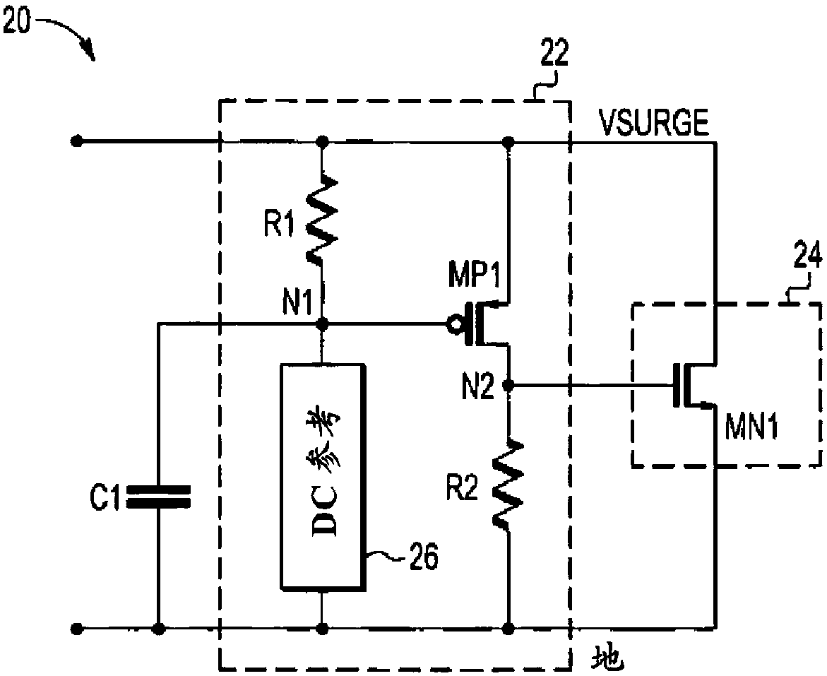
[0015] figure 2 is a schematic circuit diagram of the surge protection circuit 20 . The surge protection circuit 20 includes a DC trigger circuit 22 and a surge protection device 24 . The DC trigger circuit 22 includes first and second resistors R1 and R2 , a P-type transistor MP1 and a DC reference 26 . The surge protection circuit 20 also includes an AC trigger circuit, similar to the AC trigger circuit 12 of FIG. 1 , the AC trigger circuit includes first and second resistors R1 and R2 , a first capacitor C1 , and a P-type transistor MP1 .

[0016] like figure 2 As shown, the first resistor R1 and the first capacitor C1 are connected in series between the node Vsurge and ground. The transistor MP1 and the second resistor R2 are connected in series with each other and in parallel with the first resistor R1 and the first capacitor C1. The DC reference 26 is connected between the first node N1 and ground. The first node N1 is a point between the first resistor R1 and the f...


PUM


Abstract

The invention discloses a surge protection circuit having the feedback control function. The surge protection circuit comprises a DC trigger circuit and a surge protection device connected with the DCtrigger circuit, when surge pulse occurs, a trigger signal is generated by the DC trigger circuit, a clamping voltage taken as an output voltage of the surge protection circuit is generated by the surge protection device for responding to the trigger signal, the surge current is conducted to the ground, a feedback circuit is arranged between the surge protection device and the DC trigger circuit,and the clamping voltage is reduced through the feedback circuit so that the clamping voltage does not surpass a fault voltage of the surge protection device.

Description

technical field [0001] The present invention relates to protection circuits, and more particularly, to on-chip surge protection circuits. Background technique [0002] Current and voltage spikes (ie, energy spikes) can damage electronic circuits. Energy Spike A very fast, short-duration electrical transient in voltage (voltage spike), current (current spike), or transferred energy (energy spike) in an electrical circuit. Such spikes may be caused by, for example, electrostatic discharge (ESD) events. An uninterrupted voltage increase that usually lasts about 50uSec is called a "voltage surge" rather than a spike. Because voltage spikes and surges can damage sensitive electronics, many circuits include ESD and surge protection circuitry. [0003] FIG. 1 is a schematic circuit diagram of a conventional ESD protection circuit 10 including an AC trigger circuit 12 and an ESD protection device 14 . The AC trigger circuit 12 includes first and second resistors R1 and R2, a cap...

Claims


Application Information

Patent Timeline
IPC IPC(8): H02H9/04
CPCH02H9/04H02H9/041
Inventor 唐圣兰卿健段新东
Owner NXP BV
Why Eureka
Try Eureka