Applicable type cell float charger

A floating charger and battery technology, applied in the field of electronics, can solve the problems of not being scientific enough, not realizing charging, etc.

Inactive Publication Date: 2018-05-25
CHONGQING NINGLAI SCI & TRADE
View PDF0 Cites 0 Cited by
  • Summary
  • Abstract
  • Description
  • Claims
  • Application Information

AI Technical Summary

Problems solved by technology

[0004] The reason why the most scientific charging has not been realized is that the current products either only use DC to charge the battery, but do not use a better method, such as constant current charging; or although they can be charged with a constant current source, However, there are still some conveniences in use, or it is not scientific enough on the line, etc., so it should be enriched and developed

Method used


Image

  • Applicable type cell float charger
  • Applicable type cell float charger
  • Applicable type cell float charger

Examples


Embodiment Construction

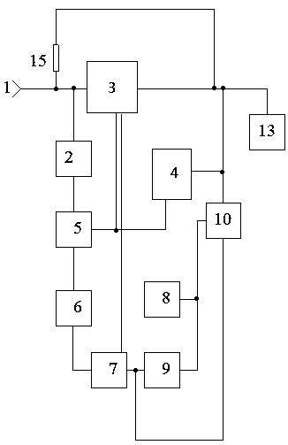
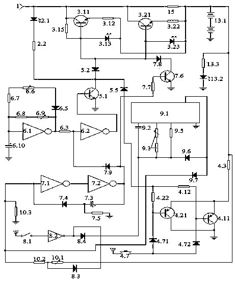
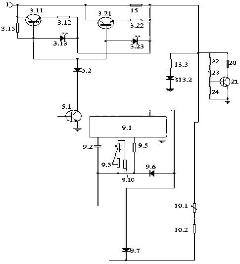
[0102] figure 1 , figure 2 An example of an implementation artifact is given, image 3 Example of detection map in implementation.

[0103] 1. Select components: 1. The power of the discharge resistor is ≥1W.

[0104] 2. The counter is an integrated circuit CD4060 composed of an oscillator and a binary serial counter.

[0105] 3. The inverters all use Schmidt NOT gates.

[0106] 4. The two constant current transistors are NPN transistors.

[0107] 5. The two discharge transistors are PNP transistors.

[0108] 2. Make the circuit control board, welding components: connect figure 2 Make the circuit control board according to the schematic diagram, connect figure 2 Schematic of soldered components.

[0109] 3. Power-on inspection and debugging.

[0110] Check that the welding is correct, and you can conduct power-on inspection and debugging.

[0111] 1. Check the constant current source part.

[0112] Such as image 3 Solder a dummy load in place of the battery being...


PUM


Abstract

The invention relates to an applicable type cell float charger and belongs to the electronic technology field. The applicable type cell float charger comprises a constant current charging unit, a discharging unit, an interface unit, a pulse unit, a selection unit, a counting unit, a voltage limiting starting unit, a load unit, a process indicator unit, an ending unit and a trickle resistor, wherein the constant current charging unit, the discharging unit, the pulse unit and the interface unit commonly form a charging/discharging pulse charging mode, the charging time is longer than the discharging time, a triode of the constant current charging unit is in a constant current mode, so constant current charging is realized. The float charger is advantaged in that an ending mode after fully charging of a cell and an ending mode after timed counting in place are employed and are two flexible conversion modes, the needed trickle current is provided by the trickle resistor to the charged cellafter charging ending, a discharging cut-off switch is arranged in the discharging unit, charging flexibility is realized, after enforcement, scientific and maximum charging of the charging cell is realized, and service life and the capacity of the charger and the charged cell are improved to the maximum degree.

Description

technical field [0001] It belongs to the field of electronic technology. Background technique [0002] Our company applied for a series of security products some time ago, and this product must have a backup battery, otherwise, when there is no mains power, the security function will become a fake, and when there is no mains power, it may be the peak of security accidents when. So a backup battery is required. And the performance of the backup battery is directly related to the overall performance. [0003] But the backup battery must be charged and maintained, and the scientific maintenance of the backup battery is directly related to the life and capacity of the backup battery. Some sources believe that batteries are often not worn out, but damaged due to improper charging. Batteries in security equipment are special-purpose batteries, which have special requirements for volume and capacity, and are more demanding than general products. [0004] The reason why the mos...

Claims


Application Information

Patent Timeline
Patent Type & Authority Applications(China)
IPC IPC(8): H02J7/00
CPCH02J7/00H02J7/0047H02J7/00711
Inventor 不公告发明人
Owner CHONGQING NINGLAI SCI & TRADE
Why Eureka
Try Eureka