Detection and braking integrated robot joint driver

A technology of robot joints and drives, which is applied in the direction of program control manipulators, manipulators, manufacturing tools, etc., can solve the problem that is not conducive to the simplification of structure and the improvement of reliability of compact system, and is not conducive to the improvement of reliability of system simplification and compaction , unable to accurately detect the actual output angle of the driver, etc., to achieve perfect reliability, compact and simple mechanical structure, simple electrical design and layout

Pending Publication Date: 2018-05-29
NANJING UNIV OF AERONAUTICS & ASTRONAUTICS
View PDF10 Cites 11 Cited by
  • Summary
  • Abstract
  • Description
  • Claims
  • Application Information

AI Technical Summary

Problems solved by technology

The limitation of the mechanical structure and the high requirements for the braking force make the size and power consumption of the brake too large, which is not conducive to the simplification and compactness of the structure and the improvement of the system reliability.
[0005] In terms of angle detection, if a sensor configuration scheme directly connected to the drive motor is used, such as a traditional servo motor, the actual output angle of the drive cannot be accurately detected when the gear ratio error, backlash and backlash of the reducer are unavoidable ; If the scheme of setting an independent angle sensor at the output shaft of the driver or the load is adopted, the complexity of the mechanical structure and the electrical circuit will be increased, which is also not conducive to the simplification and compactness of the structure and the improvement of system reliability
[0006] In summary, the traditional robot joint driver designed with separate drive system, detection system, and braking system has problems with complex mechanical structure, assembly method, and electrical circuit, resulting in low system integration and reliability.

Method used


Image

  • Detection and braking integrated robot joint driver
  • Detection and braking integrated robot joint driver
  • Detection and braking integrated robot joint driver

Examples


Embodiment Construction

[0032] In order to enable those skilled in the art to better understand the technical solutions of the present invention, the present invention will be further described in detail below in conjunction with specific embodiments.

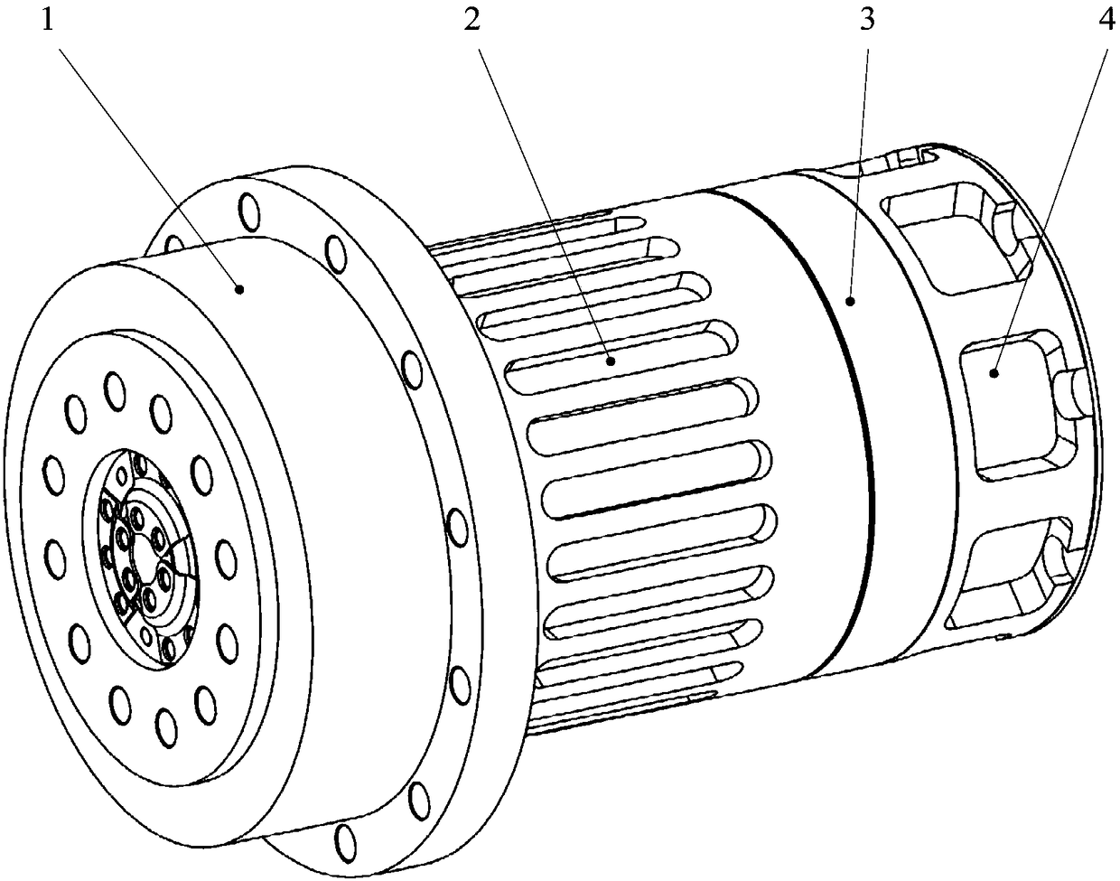
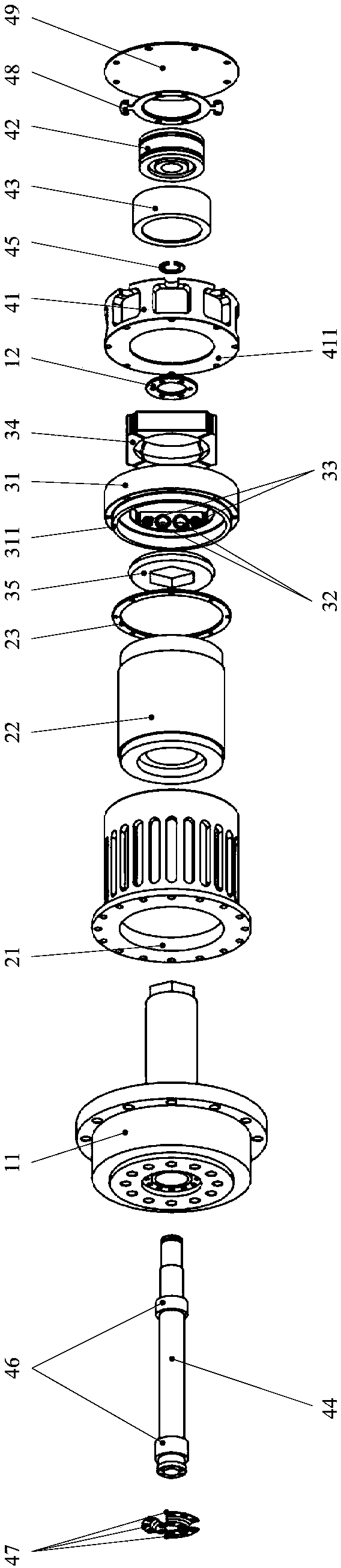
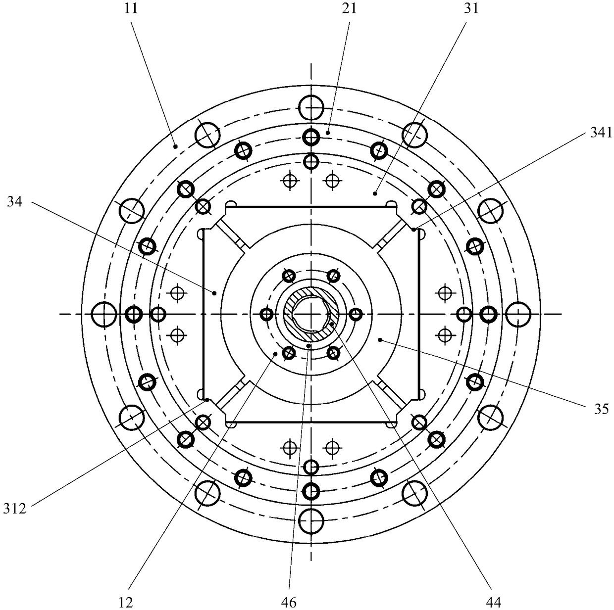
[0033] Embodiments of the present invention provide a detection and braking integrated robot joint driver, such as figure 1 with figure 2 As shown, it includes: a deceleration assembly 1 , a driving assembly 2 , a braking assembly 3 and an angle detection assembly 4 .

[0034] The deceleration assembly 1 includes a decelerator 11 and a friction block retaining ring 12 . The reducer input shaft 111 is a hollow structure, and its end section is a regular polygon, and threaded holes are evenly arranged on the end face along the circumferential direction. The friction block retaining ring 12 and the reducer input shaft 111 are connected through screws and threaded holes.

[0035] Drive assembly 2 comprises motor housing 21, motor 22 and motor fixing sn...


PUM


Abstract

The invention discloses a detection and braking integrated robot joint driver and relates to the field of industrial control. The detection and braking integrated robot joint driver comprises a speedreducing assembly, a driving assembly, a braking assembly and an angle detection assembly, and a reducer input shaft in the speed reducing assembly penetrates through and integrates the driving assembly, the braking assembly and the angle detection assembly, so that a mechanical structure of the detection and braking integrated robot joint driver is compact and concise; the compact mechanical structure allows electrical design and configuration of the detection and braking integrated robot joint driver to be relatively simple; with the adoption of a speed reducer input shaft coaxial mounting manner, an angle sensor detects more precisely, braking force of a friction block is applied more directly and uniformly, the braking stability is better, and the reliability of the detection and braking integrated robot joint driver is improved integrally; through the use of an elastic component in the detection and braking integrated robot joint driver, an unavoidable error in use and assembly ofthe detection and braking integrated robot joint driver is compensated smartly, and the reliability of the detection and braking integrated robot joint driver is further perfected; in conclusion, themechanical structure assembly mode of the detection and braking integrated robot joint driver can be integrated, the electrical design is simplified and the integrated level and reliability are improved.

Description

technical field [0001] The invention relates to the field of industrial control, in particular to a detection and braking integrated robot joint driver. Background technique [0002] In some special application scenarios such as precision manufacturing and moon / Mars rovers, the motion control of the robot not only requires the precise motion trajectory of each joint, but also requires the position to be locked immediately after the circuit is disconnected artificially or accidentally, so as to maintain the current state. The attitude of the whole machine is released, and the lock is released after the power is turned on again, and the normal driving is resumed. [0003] At present, in the robot joint driver, the motor drive system, the output angle detection system, and the braking system are mostly designed separately from each other, which makes the mechanical structure, assembly process and electrical circuit more complicated, thus affecting the integration and reliabilit...

Claims


Application Information

Patent Timeline
Patent Type & Authority Applications(China)
IPC IPC(8): B25J9/10B25J9/12B25J17/00B25J19/02
CPCB25J9/101B25J9/126B25J17/00B25J19/02
Inventor 贾山陈金宝居鹤华
Owner NANJING UNIV OF AERONAUTICS & ASTRONAUTICS
Why Eureka
Try Eureka