Heat-conducting adhesive tape

A tape and adhesive layer technology, applied in the direction of adhesives, film/sheet adhesives, etc., can solve the problems of poor heat dissipation of thermally conductive tapes, and achieve the effects of avoiding poor reworkability, improving overall performance, and improving impedance performance

Inactive Publication Date: 2018-05-29
ZHANGJIAGANG KANGDE XIN OPTRONICS MATERIAL
View PDF3 Cites 4 Cited by
  • Summary
  • Abstract
  • Description
  • Claims
  • Application Information

AI Technical Summary

Problems solved by technology

[0004] The object of the present invention is to provide a thermally conductive tape, which solves the problem of poor heat dissipation effect of the existing thermally conductive tape

Method used


Image

  • Heat-conducting adhesive tape
  • Heat-conducting adhesive tape
  • Heat-conducting adhesive tape

Examples


Embodiment 1

[0076] A thermally conductive tape:

[0077] To prepare the foam:

[0078] Vacuum dehydration of polyether polyol at 130-140 ℃, moisture content is less than 0.3%, polyether polyol (molecular weight: 1000, hydroxyl value: 110) 100 parts, MDI 35 parts, water (foaming agent): 1.5 parts, stannous octoate (catalyst): 0.5 part, silicone oil: 2 parts, carbon nanotubes 5 parts, reaction temperature 80-82 ℃, reaction 10min, and then directly poured on copper foil, copper foil is rolled copper with a thickness of 9μm foil.

[0079] On the other side of the copper foil, a slot die was used to coat the PSA with a coating thickness of 10 μm, and then a release film was attached and wound.

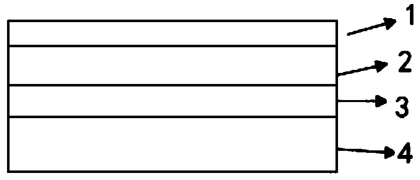
[0080] The final structure is as figure 1 As shown, it includes a release film 1, a PSA layer 2, a copper foil 3, and a foam layer 4 in sequence.

Embodiment 2

[0082] The main difference from Example 1 is that the composition of the foam is different, as follows.

[0083] To prepare the foam:

[0084] Vacuum dehydration of polyether polyol at 130-140°C, moisture content is less than 0.3%, polyether polyol (molecular weight: 1000, hydroxyl value: 110) 100 parts, MDI 30 parts, water (foaming agent): 2 parts, stannous octoate (catalyst): 0.3 parts, silicone oil: 2.5 parts, 4 parts of carbon nanotubes, 6 parts of 2,3-dibromopropanol, the reaction temperature is 88-90 ℃, the reaction is 5min, and then directly poured onto the copper foil Above, the copper foil is a rolled copper foil with a thickness of 9 μm.

[0085] On the other side of the copper foil, a slot die was used to coat the PSA with a coating thickness of 10 μm, and then a release film was attached and wound.

Embodiment 3

[0087] The main difference from Example 1 is that the composition of the foam is different, as follows.

[0088] To prepare the foam:

[0089] Vacuum dehydration of polyether polyol at 130-140 ° C, moisture content is less than 0.3%, polyether polyol (molecular weight: 1000, hydroxyl value: 110) 100 parts, MDI 40 parts, water (foaming agent): 1 part, stannous octoate (catalyst): 0.8 part, silicone oil: 1.5 part, 6 parts of carbon nanotubes, 4 parts of 2,3-dibromopropanol, reaction temperature 88-90 ℃, reaction 5min, and then directly poured into copper On the foil, the copper foil is a rolled copper foil with a thickness of 9 μm.

[0090] On the other side of the copper foil, a slot die was used to coat the PSA with a coating thickness of 10 μm, and then a release film was attached and wound.


PUM

PropertyMeasurementUnit
impedanceaaaaaaaaaa
thicknessaaaaaaaaaa
thicknessaaaaaaaaaa

Abstract

The invention provides a heat-conducting adhesive tape. The heat-conducting adhesive tape comprises a release film, an adhesive layer, a metal foil and foam which are sequentially adhered to one another, wherein the foam is adhered to the metal foil in a pouring manner; the foam layer is prepared by performing mixed foaming on the following materials in parts by weight: 100 parts of polyether polyol, 25-40 parts of diphenylmethane diisocyanate, 0.8-2 parts of water, 0.3-1 part of a catalyst and 1-2.5 parts of silicone oil, wherein the hydroxyl value of the polyether polyol is 80-140. Comparedwith the prior art, the heat-conducting adhesive tape has the characteristics as follows: 1, a pressure-sensitive adhesive is not required to be used for bonding the metal foil and the foam, and the metal foil and the foam are bonded into a whole in a pouring manner, so that the problem of reduction in overall heat dissipation, caused by introduction of the pressure-sensitive adhesive, is avoided;2, the impedance of the foam is improved.

Description

technical field [0001] The invention relates to the technical field of adhesive tapes, in particular to a thermal conductive adhesive tape. Background technique [0002] In the components of electronic equipment, thermal conductive tape is a necessary film material, which mainly plays the role of heat conduction. With the rapid development of electronic equipment, the current thermal conductive tape tends to be multi-functional, in addition to thermal conductivity, it also has functions such as enhancement and anti-fragmentation. Taking the anti-fragmentation thermal conductive tape as an example, the general structure is: the copper foil and the foam are pasted together by PSA; however, since the pasting requires a certain thickness of PSA, and PSA is a polymer compound, the thermal conductivity is low, so , reducing the overall cooling effect. [0003] In view of this, the present invention is proposed. SUMMARY OF THE INVENTION [0004] The purpose of the present inve...

Claims


Application Information

Patent Timeline
Patent Type & Authority Applications(China)
IPC IPC(8): C09J7/29C08G18/48C08K7/24C08J9/08C08G101/00
CPCC08G18/48C08K7/24C08K2201/011C09J2400/163C09J2400/243C09J2475/006C09J2301/302C08G2110/0083
Inventor 李长顺
Owner ZHANGJIAGANG KANGDE XIN OPTRONICS MATERIAL
Why Eureka
Try Eureka