Design method for horizontal-pushing-type dovetail joint assembly-type frame nodes of square steel tube column and H-shaped beam

A technology of square steel pipe and dovetail tenon, which is applied in the field of joint design of square steel pipe column and I-beam flat-push dovetail tenon assembly frame, can solve the problems of difficult beam-column joint connection technology and difficult replacement or reuse of components, and achieve Reduce the difficulty of bolt installation and accuracy deviation, the effect of simple design and low cost

Inactive Publication Date: 2018-05-29
XIAMEN UNIV
View PDF7 Cites 2 Cited by
  • Summary
  • Abstract
  • Description
  • Claims
  • Application Information

AI Technical Summary

Problems solved by technology

[0004] The purpose of the present invention is to solve the problems of difficult beam-column joint connection technology and difficult replacement or reuse of components in the on-site installation of steel structures, provide simple and convenient installation and construction, good mechanical performance, reliability and safety, and effectively improve on-site construction. The design method of square steel pipe column and I-beam flat-push dovetail tenon assembly frame joint design method with high efficiency and joint safety at the same time

Method used


Image

  • Design method for horizontal-pushing-type dovetail joint assembly-type frame nodes of square steel tube column and H-shaped beam
  • Design method for horizontal-pushing-type dovetail joint assembly-type frame nodes of square steel tube column and H-shaped beam
  • Design method for horizontal-pushing-type dovetail joint assembly-type frame nodes of square steel tube column and H-shaped beam

Examples


Embodiment Construction

[0025] In order to better understand the technical content and installation process of the present invention, it is introduced in conjunction with the accompanying drawings.

[0026] Step 1. Factory prefabricated frame beams and frame columns, and prefabricated connecting components.

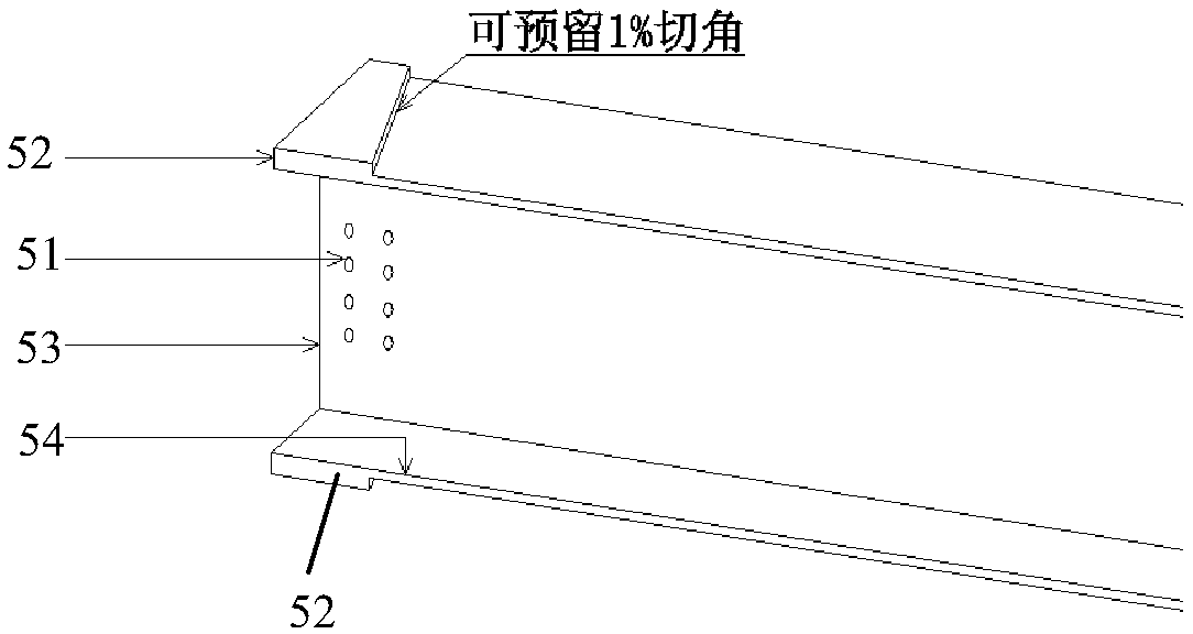
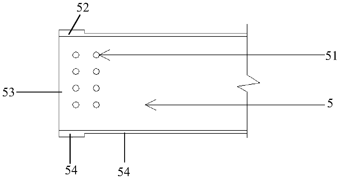
[0027] 1.1. Both the upper and lower flanges of the frame beam end are doubled and thickened by valgus to form a dovetail tenon, which is used to connect and anastomose the column shoulder joint beam mortise, such as figure 1 , 2 shown. There are several reference methods for valgus measures: add an iron plate of equal width and thickness to the position of the normal I-beam beam end; cut off the flange at the position of the tenon at the end of the beam, and weld a dovetail tenon steel plate twice the thickness of the beam flange ; Take the method of binding to process the shape of the dovetail tenon.
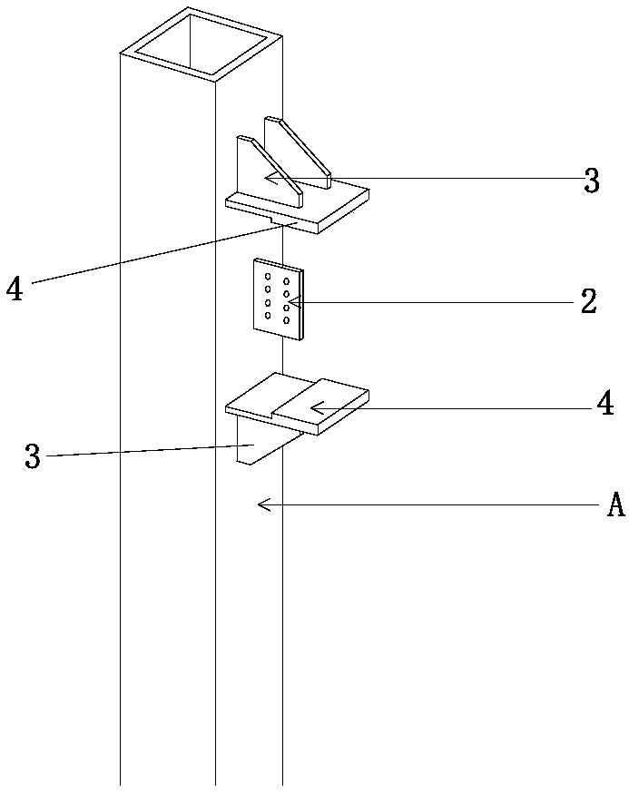
[0028] 1.2. The joint area of ​​the A-end of the square steel pipe column must be prefabr...


PUM


Abstract

The invention relates to a design method for horizontal-pushing-type dovetail joint assembly-type frame nodes of a square steel tube column and an H-shaped beam. The method comprises the steps that the square steel tube column and the H-shaped beam are processed and prefabricated, conveyed to a site, hoisted on site, and installed through bolts; a column-in clapboard, a web connection plate, a stiffening plate and a connection beam mortise component are prefabricated in a square steel tube column node area and embedded in the square steel tube column, the stress of the reinforcement square steel tube column is stable, and an auxiliary steel beam bears the bending moment which is transmitted by a connection beam mortise; the stiffening plate is a steel plate in a shape similar to the triangle, the upper and lower portions of the stiffening plate are connected with a fixing column web and the connection beam mortise, and the thickness of the stiffening plate is slightly higher than thatof the thin edge of the connection beam mortise; frame beams are connected to upper and lower flanges of the connection beam mortise in the thickness direction, the inward turning portion of the mortise is thickened twice, and the total length of the mortise is half of the height of the frame beams; the upper and lower flanges of the frame beams are outward turned and thickened twice, and dovetailjoints are formed; through prefabricated components, based on the design of mortise and tenon construction, the H-shaped beam is hoisted to a corresponding position and horizontally inserted in a column end mortise, a crane is removed, the H-shaped beam is kept stable under the effect of mortise and tenon components, and screwing-up operation is completed.

Description

technical field [0001] The invention relates to the connection and assembly of beam-column joints in a prefabricated assembled steel structure, in particular to a design method for joints of a square steel pipe column and an I-beam flat-push dovetail-tenon assembled frame based on a dovetail form. Background technique [0002] Prefabricated buildings refer to buildings assembled on site with prefabricated components. The advantage of this kind of building is that the construction speed is fast, it is less restricted by climatic conditions, it saves labor and can improve the construction quality. my country is vigorously developing prefabricated buildings and promoting the adjustment and upgrading of industrial structure. However, at present, the on-site splicing joints of fabricated steel structures in my country are still welded after on-site hoisting or multi-high-strength bolt connections. There are problems such as low on-site assembly efficiency, difficult construction...

Claims


Application Information

Patent Timeline
Patent Type & Authority Applications(China)
IPC IPC(8): E04B1/24E04B1/58
CPCE04B1/2403E04B2001/2406E04B2001/2418E04B2001/2454
Inventor 张鹏程洪阳洲
Owner XIAMEN UNIV
Why Eureka
Try Eureka