Speed reducer structure and robot with same

A reducer and pin-tooth technology, which is applied in the reducer structure and the field of robots with it, can solve the problems of easy deformation of the pin-tooth, and achieve the effects of lubrication, full contact and meshing, and reduced deflection angle

Pending Publication Date: 2018-05-29
ZHUHAI GREE REFRIGERATION TECH CENT OF ENERGY SAVING & ENVIRONMENTAL PROTECTION
View PDF5 Cites 4 Cited by
  • Summary
  • Abstract
  • Description
  • Claims
  • Application Information

AI Technical Summary

Problems solved by technology

[0004] The main purpose of the present invention is to provide a reducer structure and a robot with it, so as to solve the problem that the pin teeth are easily deformed in the prior art

Method used


Image

  • Speed reducer structure and robot with same
  • Speed reducer structure and robot with same
  • Speed reducer structure and robot with same

Examples


Embodiment Construction

[0028] It should be noted that the embodiments in this application and the features in the embodiments can be combined with each other if there is no conflict. Hereinafter, the present invention will be described in detail with reference to the drawings and in conjunction with the embodiments.

[0029] Combine Figure 1 to Figure 3 As shown, according to an embodiment of the present invention, a reducer structure is provided.

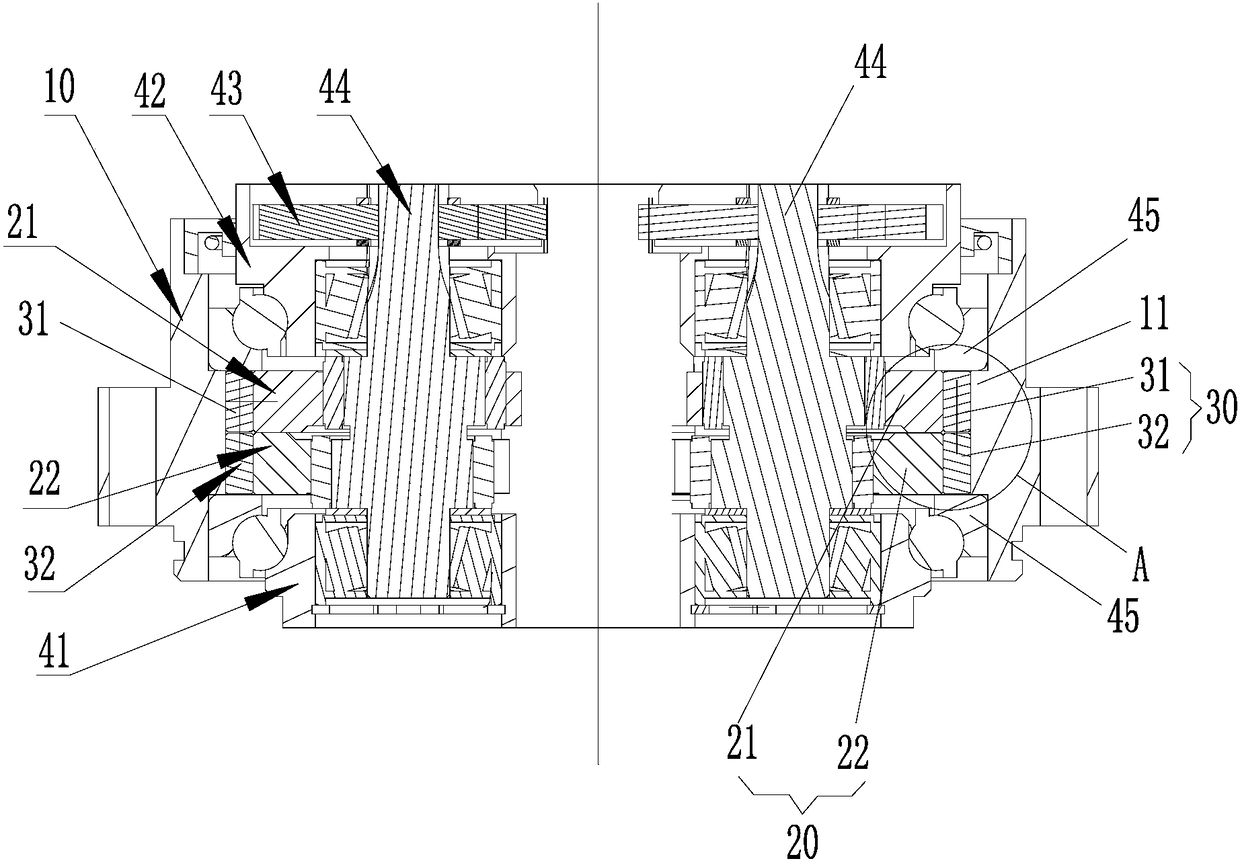
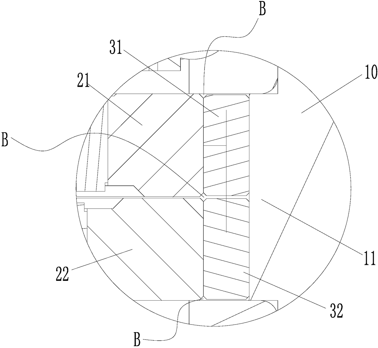
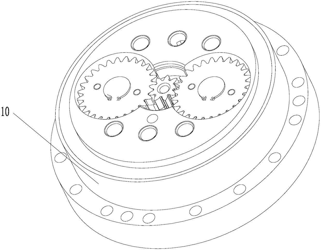
[0030] Specifically, the speed reducer structure includes a needle tooth groove 10, a cycloid assembly 20 and a needle tooth part 30. The inner wall of the needle tooth groove 10 is provided with a needle tooth groove. The cycloid assembly 20 is arranged in the needle tooth groove 10. The needle tooth portion 30 includes a first needle tooth 31 and a second needle tooth 32. The first needle tooth 31 and the second needle tooth 32 are arranged in the needle tooth groove and located on the outer peripheral surface of the cycloid assembly 20 and the groove o...


PUM


Abstract

The invention provides a speed reducer structure and a robot with the same. The speed reducer structure comprises a needle tooth groove, a cycloidal wheel module and a needle tooth part; and the needle tooth groove is formed in the inner wall of the needle tooth groove. The cycloidal wheel module is arranged in the needle tooth groove. The needle tooth part comprises a first needle tooth and a second needle tooth; and the first needle tooth and the second needle tooth are arranged in the needle tooth groove, and are positioned between the outer peripheral surface of the cycloidal wheel moduleand the groove bottom of the needle tooth groove. The needle tooth part adopts split needle teeth: the first needle tooth and the second needle tooth, so that the cycloidal wheel module and the splitneedle teeth are relatively independent during acting, and deflection angles of the needle teeth are effectively reduced. When one cycloid in the cycloidal wheel module is engaged with the needle teeth for stressing, as the lengths of axes of the needle teeth are reduced, the contacted areas of the needle teeth with the cycloids are not influenced by needle tooth holes or cycloidal profile axis machining errors, and full contacted engagement is realized. In addition, the split needle teeth are adopted; and the two split needle teeth form a gap channel in the connecting place to facilitate lubrication of the needle teeth.

Description

Technical field [0001] The present invention relates to the technical field of reducer equipment, and in particular to a reducer structure and a robot having the same. Background technique [0002] Traditional RV reducers have the characteristics of large transmission ratio, large output torque, high efficiency, high precision, and stable operation. They are mainly used for transmission equipment with low speed and high torque output. The pin tooth structure of the RV reducer is a cylindrical structure, and each pin tooth acts simultaneously with two cycloidal wheels during operation. However, the cylindrical pin tooth structure will mesh with the cycloidal gear and cause insufficient lubrication. During transmission, the contact area with the pin teeth decreases after the cycloidal gear is deformed by force, and the stress and strain increase, which increases the wear and deformation of the cycloidal gear. Larger, reduced service life and reduced movement accuracy. There may e...

Claims


Application Information

Patent Timeline
Patent Type & Authority Applications(China)
IPC IPC(8): F16H1/32F16H55/08F16H55/12F16H57/04
CPCF16H1/32F16H55/08F16H55/12F16H57/0464F16H57/0479F16H57/0486F16H2057/02039
Inventor 程中甫崔中刘成杨方元胡余生魏会军郭霜许甲岿田珍珍
Owner ZHUHAI GREE REFRIGERATION TECH CENT OF ENERGY SAVING & ENVIRONMENTAL PROTECTION
Why Eureka
Try Eureka