
Flexible trailing edge structure and design method thereof

A flexible wing and structural design technology, applied in the wing field, can solve the problems of increased structural weight, difficulty in use, bulky reliability, etc., and achieve the effect of continuous flexible deformation, simple configuration, and light weight

Active Publication Date: 2018-05-29
CHINA AIRPLANT STRENGTH RES INST
View PDF7 Cites 20 Cited by
  • Summary
  • Abstract
  • Description
  • Claims
  • Application Information

AI Technical Summary

Problems solved by technology

[0002] The traditional wing design only takes the aerodynamic efficiency under a single flight condition (cruising) as the design goal, and can only maintain high aerodynamic efficiency during cruising, and the existence of separated flaps and aileron gaps not only reduces the aerodynamic efficiency of the wing. Aerodynamic efficiency, and the sharp structure rubs against the air between the gaps, causing noise problems
[0003] The flexible wing flutter models in the prior art all use mechanical rigid hinge transmission to realize the flexible deformation of the outer contour of the wing, but the internal mechanical structure and transmission structure greatly increase the structural weight, which is cumbersome and has low reliability, so it is not easy to use in the aircraft. used in wing structure design

Method used


Image

  • Flexible trailing edge structure and design method thereof

Examples


Embodiment Construction

[0034] In order to make the objectives, technical solutions and advantages of the present invention clearer, the technical solutions in the embodiments of the present invention will be described in more detail below in conjunction with the drawings in the embodiments of the present invention. In the drawings, the same or similar reference numerals denote the same or similar elements or elements having the same or similar functions throughout. The described embodiments are some, but not all, embodiments of the invention. The embodiments described below by referring to the figures are exemplary and are intended to explain the present invention and should not be construed as limiting the present invention. Based on the embodiments of the present invention, all other embodiments obtained by persons of ordinary skill in the art without creative efforts fall within the protection scope of the present invention. Embodiments of the present invention will be described in detail below ...


PUM


Abstract

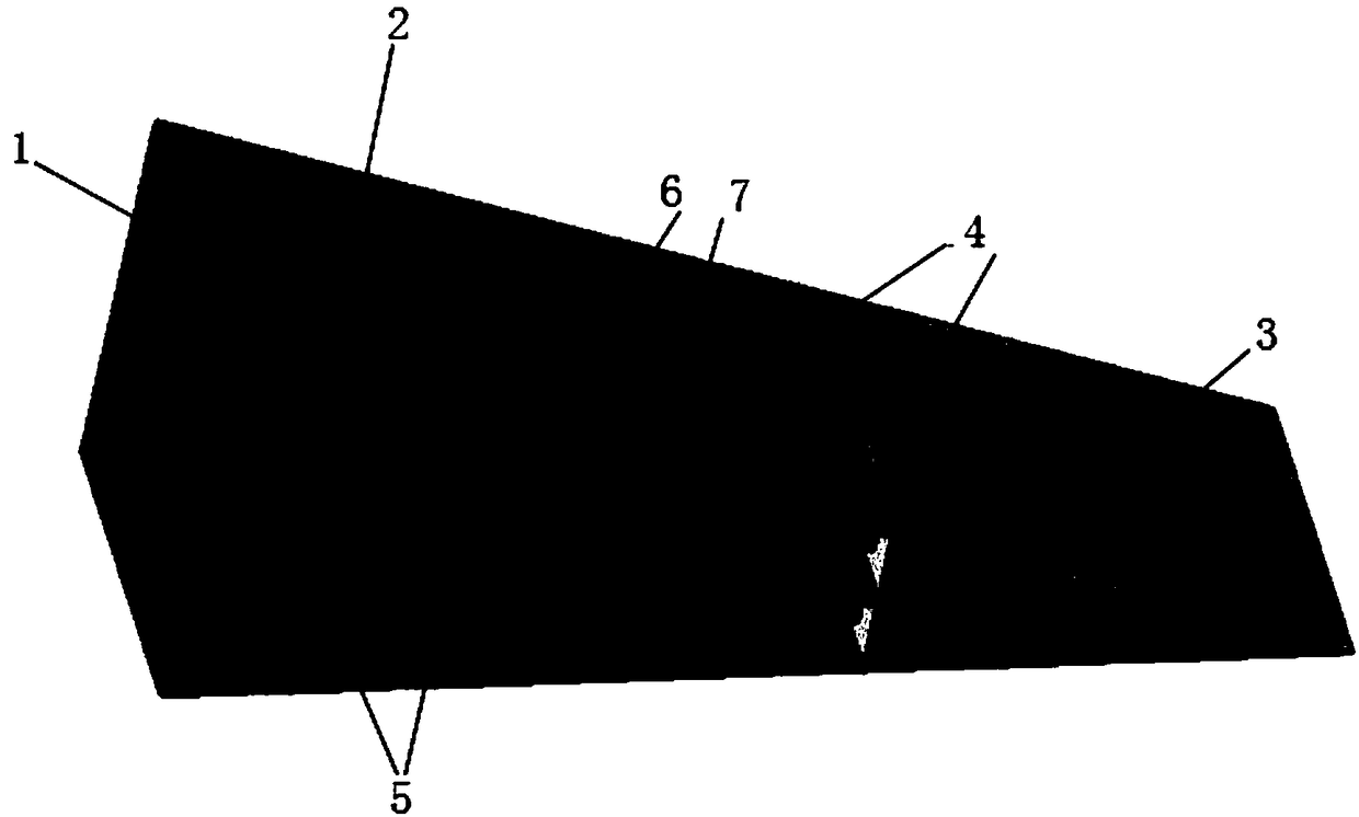
The invention discloses a flexible trailing edge structure and a design method thereof. The flexible trailing edge structure comprises a rear beam, a flat bent beam, a rigid triangular wingtip, a flexible skin, filling honeycombs, a first driver and a second driver, wherein the rear beam, the flexible skin and the rigid triangular wingtip define a containing space; the flat bent beam is arranged in the containing space and divides the containing space into a first space and a second space; the first driver is arranged in the first space; the second driver is arranged in the second space; and the filling honeycombs are arranged in the first space and the second space. The flexible trailing edge structure is low in weight and simple in configuration, meets the demands of continuous flexibledeformation and low mass of a trailing edge structure and therefore achieves the purpose of replacing a rigid flap and an aileron.

Description

technical field [0001] The invention relates to the technical field of wings, in particular to a flexible wing trailing edge structure and a design method for the flexible wing trailing edge structure. Background technique [0002] The traditional wing design only takes the aerodynamic efficiency under a single flight condition (cruising) as the design goal, and can only maintain high aerodynamic efficiency during cruising, and the existence of separated flaps and aileron gaps not only reduces the aerodynamic efficiency of the wing. Aerodynamic efficiency, and the sharp structure rubbing against the air in the gaps creates noise problems. [0003] The flutter models of flexible wings in the prior art all use mechanical rigid hinge transmission to realize the flexible deformation of the outer contour of the wing, but the internal mechanical structure and transmission structure greatly increase the structural weight, which are cumbersome and have low reliability. Used in wing...

Claims


Application Information

Patent Timeline
Patent Type & Authority Applications(China)
IPC IPC(8): G06F17/50
CPCG06F30/15G06F30/23
Inventor 杨宇张盛
Owner CHINA AIRPLANT STRENGTH RES INST
Learn More