Straw crusher with composite cutter roller

A technology of straw shredder and compound knife, which is applied to harvesters, agricultural machinery and implements, cutters, etc., can solve the problems of easily causing forest fires, affecting air quality, and difficult to operate small machinery, and achieving a compact and stable overall structure, The effect of reducing the overall weight and increasing the use value

Inactive Publication Date: 2018-06-01
重庆智恒科技咨询有限公司
View PDF0 Cites 0 Cited by
  • Summary
  • Abstract
  • Description
  • Claims
  • Application Information

AI Technical Summary

Problems solved by technology

[0002] With the development of agricultural mechanization and the improvement of environmental protection demands, the straw produced in the agricultural production process is now advocated to return the straw to the field, but because incineration usually produces a lot of smoke and dust, it will also seriously affect the air quality, so It is not advisable to return the field by burning. More and more places adopt the mechanical crushing method, and the straw can be crushed directly at the same time as harvesting. The crushed straw is kept in the original cultivated land, which is fast and convenient. Due to terrain constraints, it is difficult for small machinery to operate, let alone large machinery. This has led to the fact that in many mountainous areas, straw is basically disposed of by burning, which seriously affects air quality and is also prone to forest fires. Therefore, there is an urgent need for a straw crushing machine suitable for mountainous areas.

Method used


Image

  • Straw crusher with composite cutter roller
  • Straw crusher with composite cutter roller
  • Straw crusher with composite cutter roller

Examples


Embodiment Construction

[0021] The present invention will be further described below in conjunction with embodiment and accompanying drawing.

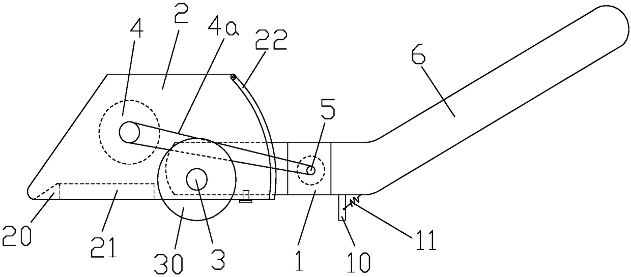
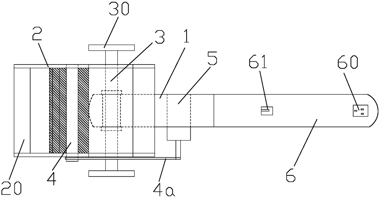
[0022] refer to Figure 1 to Figure 3 , the straw pulverizer with composite knife roller of the present invention mainly includes a frame 1 and a suspension cover 2 arranged horizontally. In the present invention, the frame 1 is a hollow cuboid columnar structure, and the front end is pierced with a wheel shaft 3, and the wheel shaft 3 is horizontal. It is arranged and perpendicular to the axial direction of the frame 1, and the wheel shaft 3 can be fixedly installed on the frame 3 without rotation.

[0023] The suspension cover 2 is detachably supported on the frame 1. In the present invention, the suspension cover 2 is surrounded by a left side plate, a right side plate, a top plate and a bottom plate, and the top plate is relatively short relative to the bottom plate, so the encirclement forms a trapezoidal cross section. Tubular structure, its front and ...


PUM


Abstract

The invention discloses a straw crusher with a composite cutter roller. The straw crusher comprises a machine frame and a suspension cover; two ends of the suspension cover are opened; the suspensioncover is provided with a wheel shaft in the width direction, two ends of the wheel shaft penetrate through side plates at two sides of the suspension cover; the two ends of the wheel shaft are provided with ground wheels; a cutter roller is rotatably arranged inside the suspension cover; blades are arranged on the cutter roller; a motor for driving the cutter roller to rotate is arranged on the machine frame; the blades comprise fixed blades and swinging blades; the fixed blades and the swinging blades are distributed along the circumferential direction of the cutter roller in a staggered way;each fixed blade comprises a vertical cutting part and a transverse cutting part which are integrally formed; the rear end of the machine frame is connected with a handle; the tail end of the handleis provided with a power supply connection port and a power switch; and the handle is internally provided with a wire connecting the power supply connection port and the motor. The cutter roller structure is novel; the crushing efficiency can be improved; the whole weight of the crusher is reduced; the flexible movement control can be carried out through manual pushing, so that the crusher is moresuitable for single-person straw crushing operation in hilly land areas; the integral structure of the crusher is compact and stable; and a great use value is achieved.

Description

technical field [0001] The invention belongs to the technical field of agricultural machinery and equipment, and in particular relates to a straw pulverizer with a composite knife roller. Background technique [0002] With the development of agricultural mechanization and the improvement of environmental protection demands, the straw produced in the agricultural production process is now advocated to return the straw to the field, but because incineration usually produces a lot of smoke and dust, it will also seriously affect the air quality, so It is not advisable to return the field by burning. More and more places adopt the mechanical crushing method, and the straw can be crushed directly at the same time as harvesting. The crushed straw is kept in the original cultivated land, which is fast and convenient. Due to terrain constraints, it is difficult for small machinery to operate, let alone large machinery. This has led to the fact that in many mountainous areas, straw i...

Claims


Application Information

Patent Timeline
Patent Type & Authority Applications(China)
IPC IPC(8): A01D34/835
CPCA01D34/8355
Inventor 王丽萍
Owner 重庆智恒科技咨询有限公司
Why Eureka
Try Eureka