Flue gas purifying and treating apparatus

A treatment device and flue gas purification technology, which is applied in combination devices, chemical instruments and methods, water shower coolers, etc., can solve the problem that the flue gas purification treatment device is difficult to meet the dust and particulate matter emission standards of industrial enterprises.

Pending Publication Date: 2018-06-01
HEIMDALLR SHANGHAI ENERGY SAVING TECH
View PDF6 Cites 3 Cited by
  • Summary
  • Abstract
  • Description
  • Claims
  • Application Information

AI Technical Summary

Problems solved by technology

[0004] In order to solve the technical problem that the existing flue gas purification treatment device is difficult to me

Method used


Image

  • Flue gas purifying and treating apparatus
  • Flue gas purifying and treating apparatus
  • Flue gas purifying and treating apparatus

Examples


Embodiment Construction

[0057] The present invention is further illustrated below by means of examples, but the present invention is not limited to the scope of the examples.

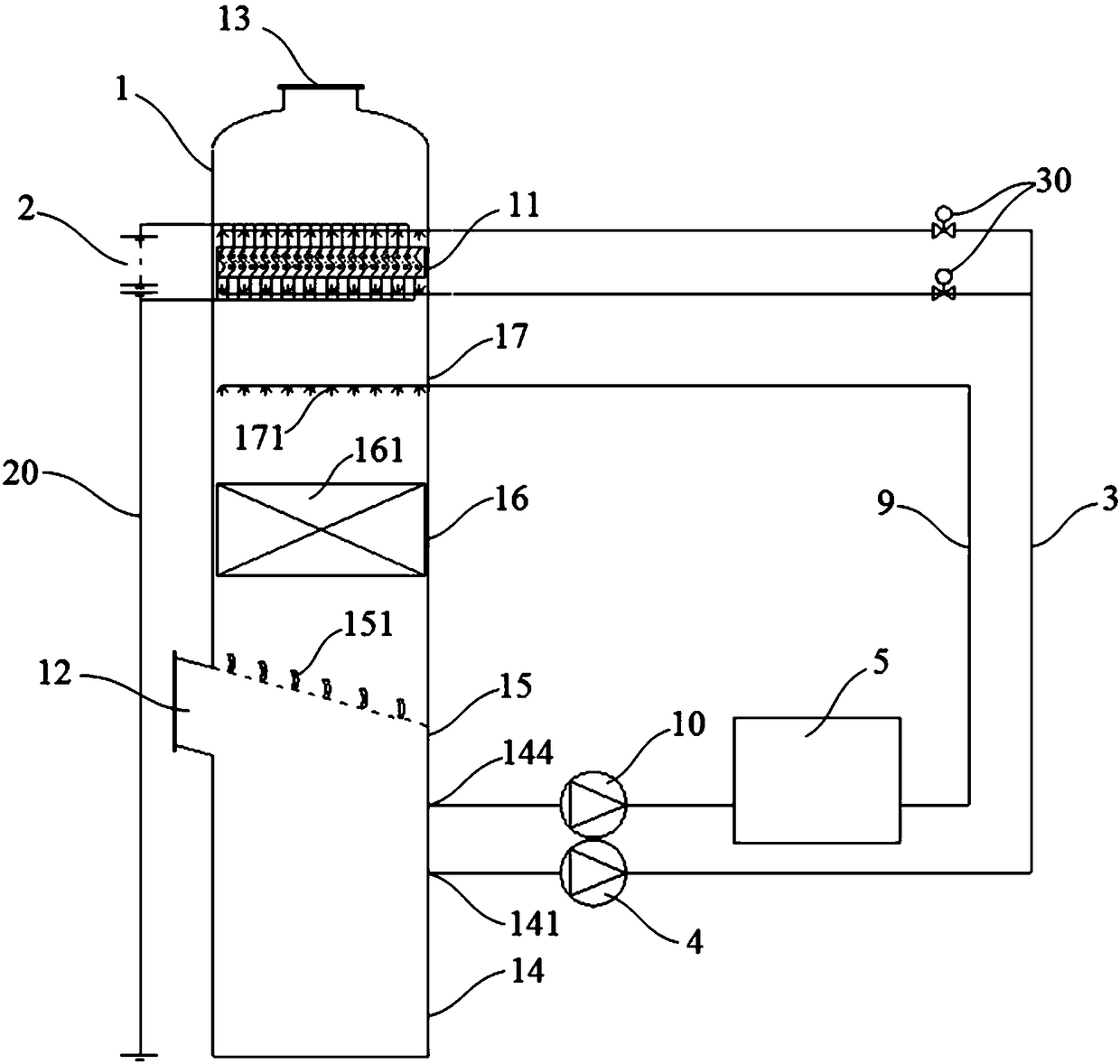
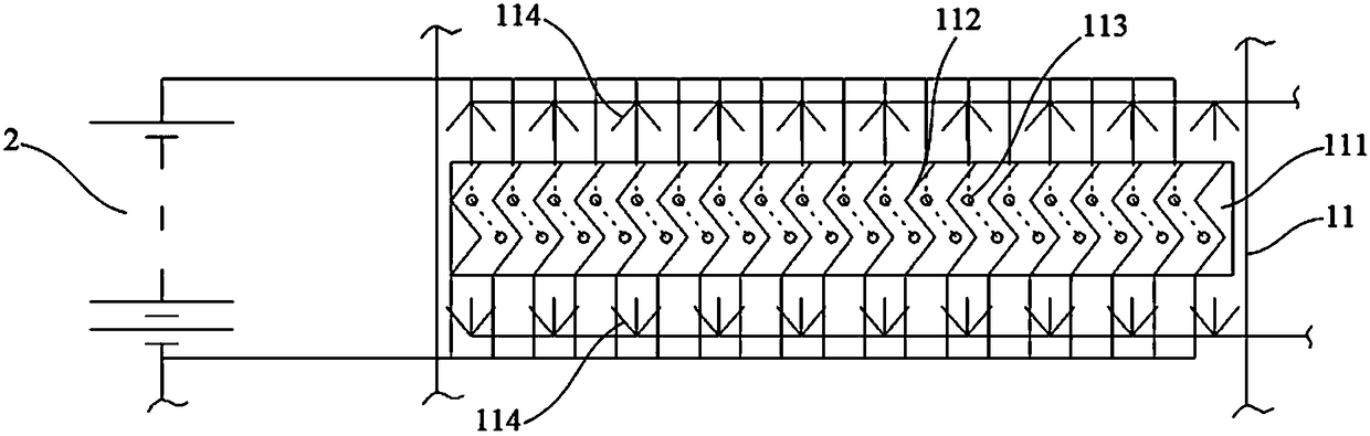
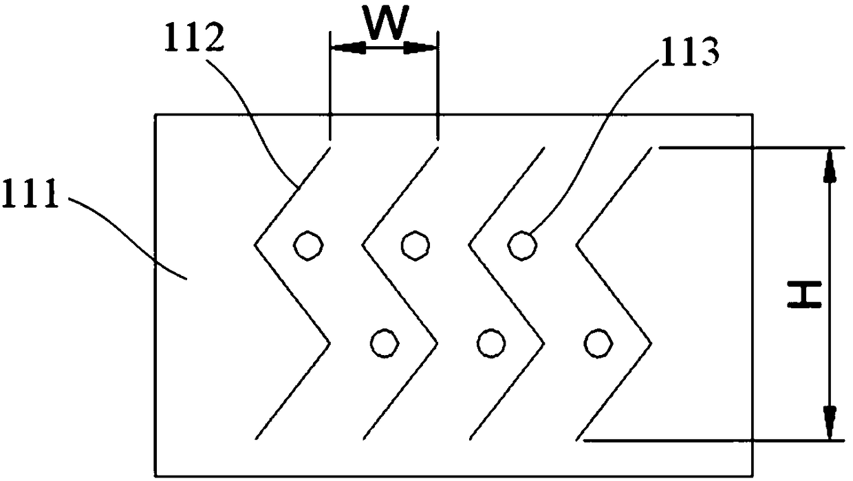
[0058] like Figure 1 to Figure 4 Shown is the first embodiment of the flue gas purification treatment device of the present invention. It includes a purification tower 1 and a power supply 2 located outside the purification tower 1. A flue gas inlet 12 and a flue gas outlet 13 are provided on the purification tower 1. The flue gas inlet 12 is located under the purification tower 1, and the flue gas outlet 13 is located at the purification tower 1. The top of the purification tower 1 is provided with an ultra-clean section 11, and the ultra-clean section 11 includes a substrate 111 positioned in the purification tower 1, a plurality of anode plates 112 fixed on the substrate 111 and a plurality of cathode wires 113, and a plurality of cathodes The wires 113 are evenly distributed between a plurality of anode plates 112, the a...


PUM

PropertyMeasurementUnit
Heightaaaaaaaaaa

Abstract

The invention provides a flue gas purifying and treating apparatus. The apparatus comprises a purification tower and a power supply which is positioned at the outer side of the purification tower, thepurification tower is opened with a flue gas inlet and a flue gas outlet, the flue gas inlet is positioned at the lower part of the purification tower, and the flue gas outlet is at the top of the purification tower; the upper part of the purification tower is provided with an ultra-cleaning section, and the ultra-cleaning section comprises a substrate which is positioned in the ultra-cleaning section, multiple anode plates and multiple cathode wires which are fixed on the substrate, multiple cathode wires are uniformly distributed between multiple anode plates, the anode plates and a cathodeof the power supply are connected, the cathode wires and an anode of the power supply are connected; multiple back flushing nozzles are arranged above and/or below the substrate. The flue gas purifying and the treating apparatus is provided with the ultra-cleaning section which is above a spraying section and comprises anode plates and cathode plates, a hygroscopic solution is used for flushing,content of flue gas dust and particles are further reduced before wet type electric precipitation, and at the same time, waste heat of the flue gas is recovered, and purposes of deep purification of flue gas and waste heat recovery are realized.

Description

technical field [0001] The invention relates to a flue gas purification treatment device. Background technique [0002] With the increasingly stringent dust and particle emission standards of industrial enterprises, existing dust removal technologies such as electrostatic precipitator, bag filter, water film dust removal, etc. Electrostatic precipitators are more widely used in pollutant emission control. [0003] However, the import conditions of the traditional wet electrostatic precipitator are harsh and need to be controlled below 30-50 mg / m, and the delay of unsaturated or completely wet flue gas will damage the dust collection environment and affect the treatment effect of the wet electrostatic precipitator. The space occupied by electrostatic precipitator is limited in the transformation process of industrial enterprises. Contents of the invention [0004] In order to solve the technical problem that the existing flue gas purification treatment device is difficult...

Claims


Application Information

Patent Timeline
IPC IPC(8): B01D50/00F28C1/08
CPCB01D50/00F28C1/08
Inventor 马元白亮徐敬玉
Owner HEIMDALLR SHANGHAI ENERGY SAVING TECH
Why Eureka
Try Eureka