Cutting device and cutting method of LED lamp panel

A technology of LED light board and cutting device, which is applied in metal processing and other directions, can solve the problems of uneven cutting of light strips, deformation and deviation of light strips, easy bending and other problems, and achieves convenient cutting operations, reduced work efficiency, and good location The effect of stability

Active Publication Date: 2018-06-01
江苏烨明光电有限公司
View PDF5 Cites 2 Cited by
  • Summary
  • Abstract
  • Description
  • Claims
  • Application Information

AI Technical Summary

Problems solved by technology

[0003] With the improvement of people's quality of life, people's requirements for lights are no longer the original lighting use. LED lights with different colors, different brightness, and different uses have attracted more and more people's attention. In the production process of LED light panels, in order to To prevent the length of the light bar from affecting the processing accuracy, resulting in deformation and offset of the light bar, multiple sets of light bars are often connected into light panels for production and processing, which not only enables mass production, but also effectively improves production and processing After the production is completed, it is necessary to divide the light board into light strips and cut them. The cutting work of the transmission is done manually. Due to factors considered by the market, the light strips are not cut neatly during cutting. , the phenomenon of easy bending, for this reason, we propose a cutting device and cutting method for LED light panels

Method used


Image

  • Cutting device and cutting method of LED lamp panel
  • Cutting device and cutting method of LED lamp panel
  • Cutting device and cutting method of LED lamp panel

Examples


Embodiment Construction

[0027] The following will clearly and completely describe the technical solutions in the embodiments of the present invention with reference to the accompanying drawings in the embodiments of the present invention. Obviously, the described embodiments are only some, not all, embodiments of the present invention. Based on the embodiments of the present invention, all other embodiments obtained by persons of ordinary skill in the art without making creative efforts belong to the protection scope of the present invention.

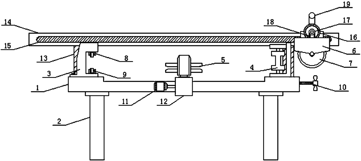
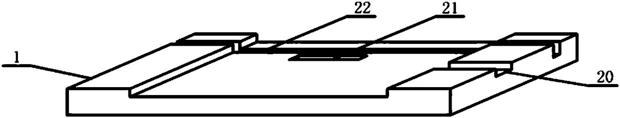
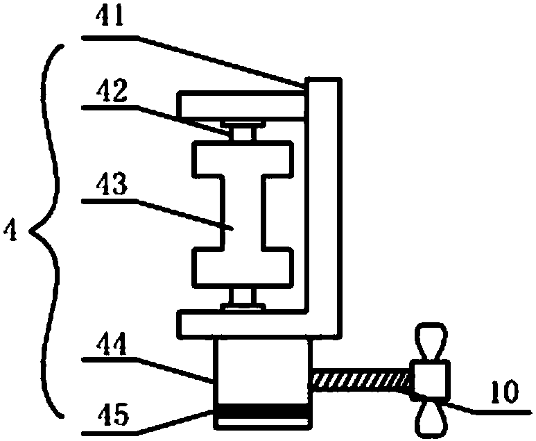
[0028] see Figure 1-5 , the present invention provides a technical solution: a cutting device for LED lamp panels, including a workbench 1, the four corners of the bottom of the workbench 1 are evenly provided with support feet 2, and the top left side of the workbench 1 is provided with Fixed spacer frame 3, the right side of described fixed spacer frame 3 has placement groove, and the groove bottom and groove top of placement groove are symmetrically provid...


PUM


Abstract

The invention discloses a cutting device of an LED lamp panel in the technical field of LEDs. The cutting device comprises a workbench, wherein the four corners of the bottom of the workbench are uniformly provided with support legs, a fixed limiting frame is arranged at the left side of the top of the workbench, and a placing groove is formed in the right side of the fixed limiting frame; two groups of small brackets with the same structure are symmetrically arranged on the groove bottom and groove top of the placing groove, and auxiliary runners are mounted on the small brackets; and a moving limiting frame is arranged at the right side of the top of the workbench, and a regulating bolt connected with the bottom of the moving limiting frame is arranged on the outer wall of the right sideof the workbench. According to the device, the shift of the lamp panel is limited through the fixed limiting frame with the auxiliary runners and the moving limiting frame with an I-shaped rotor drum, so that the lamp panel has great position stability during cutting operation, and the cutting working efficiency is prevented from being reduced by shift and bending phenomena caused by friction resistance occurring in the movement process of the lamp panel.

Description

technical field [0001] The invention relates to the technical field of LEDs, in particular to a cutting device and a cutting method for LED lamp panels. Background technique [0002] Light-emitting diodes are referred to as LEDs for short. Made of compounds containing gallium (Ga), arsenic (As), phosphorus (P), nitrogen (N), etc., when electrons and holes recombine, they can radiate visible light, so they can be used to make light-emitting diodes. As an indicator light in circuits and instruments, or as a text or digital display, gallium arsenide diodes emit red light, gallium phosphide diodes emit green light, silicon carbide diodes emit yellow light, and gallium nitride diodes emit blue light. Divided into organic light-emitting diode OLED and inorganic light-emitting diode LE. [0003] With the improvement of people's quality of life, people's requirements for lights are no longer the original lighting use. LED lights with different colors, different brightness, and dif...

Claims


Application Information

Patent Timeline
Patent Type & Authority Applications(China)
IPC IPC(8): B26D1/18B26D7/02B26D5/02
CPCB26D1/18B26D5/02B26D7/025
Inventor 董桂芳
Owner 江苏烨明光电有限公司
Why Eureka
Try Eureka