

Rapid film coating process for battery pole group
A battery pole group and fast packaging technology, applied in lead-acid batteries, lead-acid battery construction, packaging, etc., can solve the problems of cumbersome process, low coating efficiency, poor coating effect, etc., achieve good effect, ingenious structure, The effect of high production efficiency
- Summary
- Abstract
- Description
- Claims
- Application Information
AI Technical Summary
Problems solved by technology
Method used
Image

Examples
Embodiment 1
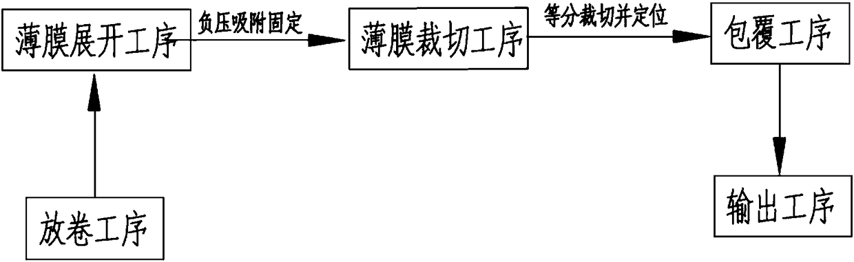
[0067] Such as figure 1 , figure 2 , image 3 , Figure 4 , Figure 5 , Figure 6 , Figure 7 , Figure 8 , Figure 9 and Figure 10 As shown, a battery electrode group rapid coating process includes the following production steps:
[0068] Step 1: the unwinding process, placing the roll film on the unwinding station, and the positioning mechanism 12 located at the unwinding station positions the end of the roll film;
[0069] Step 2: film unfolding process, the adsorption mechanism 21 moves to the unwinding station, fixes the end of the film at the positioning mechanism 12, and moves along the guide mechanism 22 under the drive of the traction mechanism 23 to fix the film after the fixing is completed. unfold;
[0070] Step 3: film cutting process, after the film is unfolded, first the cross-cutting mechanism 13 at the unwinding station cuts off the tail end of the film, and then the cutting and positioning mechanisms 31 located on both sides of the unfolded film c...
Embodiment 2
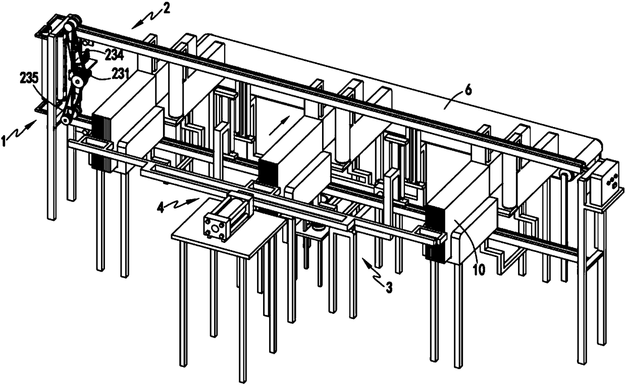
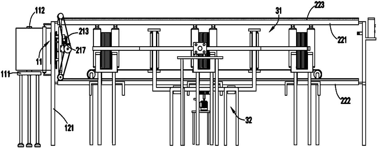
[0082] Such as figure 1 , figure 2 , image 3 , Figure 4 , Figure 5 , Figure 6 , Figure 7 , Figure 8 , Figure 9 and Figure 10 As shown, a battery pole group rapid coating system includes an unwinding device 1, and the unwinding device 1 includes an unwinding mechanism 11 for placing a roll film, and an unwinding mechanism 11 arranged on one side of the unwinding mechanism 11. A positioning mechanism 12 for positioning the end of the roll film and a cross-cutting mechanism 13 arranged on one side of the positioning mechanism 12;
[0083] The film unrolling device 2, the film unrolling device 2 includes a guide mechanism 22, an absorbing mechanism 21 arranged on the guide mechanism 22 for absorbing the end of the roll film at the positioning mechanism 12 and for driving the absorbing mechanism 21, together with the end of the roll film, moves along the guide mechanism 22 to the traction mechanism 23 that unfolds the film;
[0084] A cutting device 3, which incl...
Embodiment 3
[0104] Such as figure 1 , figure 2 , image 3 , Figure 4 , Figure 5 , Figure 6 , Figure 7 , Figure 8 , Figure 9 and Figure 10 As shown, the parts that are the same as or corresponding to those in the second embodiment are marked with the corresponding reference numerals in the second embodiment. For the sake of simplicity, only the differences from the second embodiment will be described below. The difference between the third embodiment and the second embodiment is that further, the cutting positioning mechanism 31 includes a sliding seat 311, a cutting positioning assembly a312 which is slidably arranged on the sliding seat 311 and symmetrically arranged front and rear, and a cutting positioning component b313;
[0105] The cutting positioning assembly a312 includes a slider a3121 that cooperates with the guide rod b3111 on the sliding seat 311 to slide, a connecting frame a3122 fixedly connected to the sliding block a3121, a mounting frame a3123 arranged at...
PUM
 Abstract
Description
Claims
Application Information