
Blow-off valve for steam explosion adverse working conditions and action mode

A kind of operation and harsh technology, applied in the direction of valve operation/release device, lift valve, valve details, etc., can solve the problems of incompatibility of production practice, affecting production efficiency and output quality, bulky and heavy, etc., to improve efficiency and output quality, adaptability to a wide range of working conditions, and prolong the service life of equipment

Inactive Publication Date: 2018-06-01
李肥生
View PDF4 Cites 5 Cited by
  • Summary
  • Abstract
  • Description
  • Claims
  • Application Information

AI Technical Summary

Problems solved by technology

[0004] Such as commonly used electric ball valves, gate valves, plunger valves, etc., although they have good flexibility and sealing performance, they are fundamentally derived from liquid material valves. Under harsh working conditions, they are prone to plugging and leakage due to frequent replacement. Limited by the structure, the diameter is small, the flow rate is low, and the output rate is low, which can only meet the needs of small batch tests
[0005] Another example is the "quick opening" device that is often used in the production of enterprises. Although it has a large diameter and can adapt to the characteristics of solid materials, it is bulky and heavy. It needs a motor to open and close through mechanical transmission. Forming the effect of steam explosion instant high-pressure release material explosion, which also directly affects production efficiency and output quality
[0006] There are also some so-called multi-state material valve reports in the laboratory stage, most of which are not suitable for production practice, and are vulnerable to damage and require a lot of maintenance, so it is difficult to see industrial application

Method used


Image

  • Blow-off valve for steam explosion adverse working conditions and action mode
  • Blow-off valve for steam explosion adverse working conditions and action mode
  • Blow-off valve for steam explosion adverse working conditions and action mode

Examples


example 1

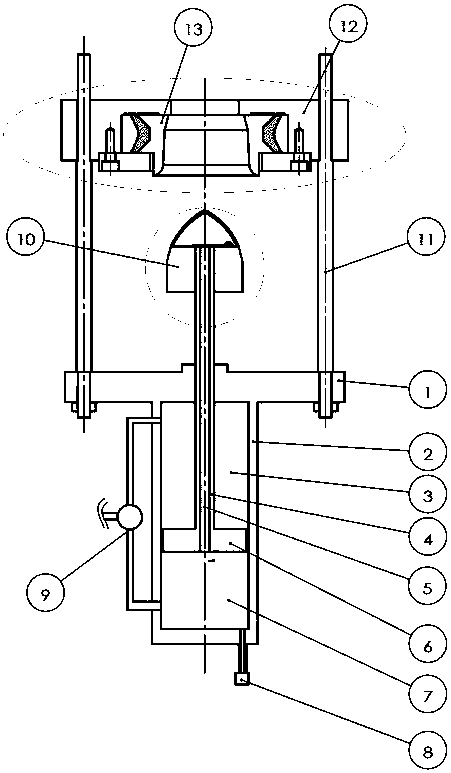
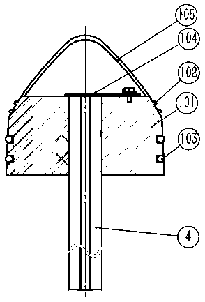
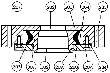
[0028] Example 1, the discharge valve is integrally assembled on the lower end surface of the discharge port at the bottom of the steam explosion tank, and the reversing valve is adjusted to inject pressure steam into the lower air chamber of the valve cylinder (the reversing valve synchronously transfers the gas leakage), the piston of the cylinder pushes the piston rod and the valve core at the rod end to move upward quickly together. At this time, part of the steam ascends through the hollow through hole of the piston rod, and the upper port of the through hole is temporarily caught by the reed in the valve core. Blocked, when the continuously and rapidly upward valve core enters the taper inner diameter of the upper valve seat and is about to contact each other, it is controlled by the buffer at the end of the cylinder stroke to move slowly, and gradually touches the tapered inner diameter of the valve seat gently while moving slowly. Force the valve seat in the valve seat ...


PUM


Abstract

The invention discloses a blow-off valve for steam explosion adverse working conditions and an action mode. The valve is of a main structure, a lower cylinder, an upper valve body, an upper valve carrier and four middle supporting columns form the main structure, and the valve is assembled on the lower end surface of a discharging port of a steam explosion tank. The valve is provided with a 'tapered plug type starting and stopping mechanism', a free body construction' and a 'pressure balancing mode', has characteristics of gas, solid and liquid substances and can blast and control biomass materials under the adverse working conditions of high temperature and pressure and polymorphism mixing, steam explosion efficiency is remarkably improved, the blow-off valve has the advantages of wide application range, good sealing performance, rapidness and stability in operation, simplicity, convenience and easiness in maintenance and long service life, and the valve can be widely used for intermittent pressure tanks and provides an ideal device section type for industrial application.

Description

technical field [0001] The invention belongs to the field of chemical equipment, and in particular relates to a discharge valve adapted to the harsh working conditions of steam explosion operations and its action mode. Background technique [0002] In industrial production, pressure vessels are widely used for high-temperature and high-pressure treatment of various materials, and the effect is obvious, but the valves that are matched with it are relatively lagging behind, and most of them are designed for a single liquid or solid or gaseous material in the early stage. control structure. With the continuous emergence of new materials and new industries, the demand for the control of three-state mixed materials is becoming stronger and stronger. Therefore, it is very important and urgent to develop special control valves suitable for multi-state mixed materials. [0003] The use of agricultural and forestry residues and wastes such as straw and fruit shells as raw materials ...

Claims


Application Information

Patent Timeline
Patent Type & Authority Applications(China)
IPC IPC(8): F16K1/00F16K1/42F16K31/122
CPCF16K1/00F16K1/422F16K31/122
Inventor 李肥生
Owner 李肥生
Learn More